5-S14
BX24, RCK54(P)-23BX, RCK60B-23BX, LA240, BT601, WSM
HYDRAULIC SYSTEM
[3] DISASSEMBLING AND ASSEMBLING
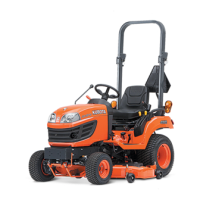
(1) Hydraulic Cylinder and Control Valve
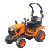
Control Valve
1. Remove the control valve (1).
2. Remove the internal snap ring (4) and draw out the spool (2).
W1030131
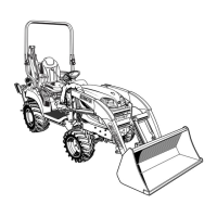
Control Valve Lever
1. Pull out the pin (1).
2. Remove the control valve lever (3) and arm (2).
W1030453
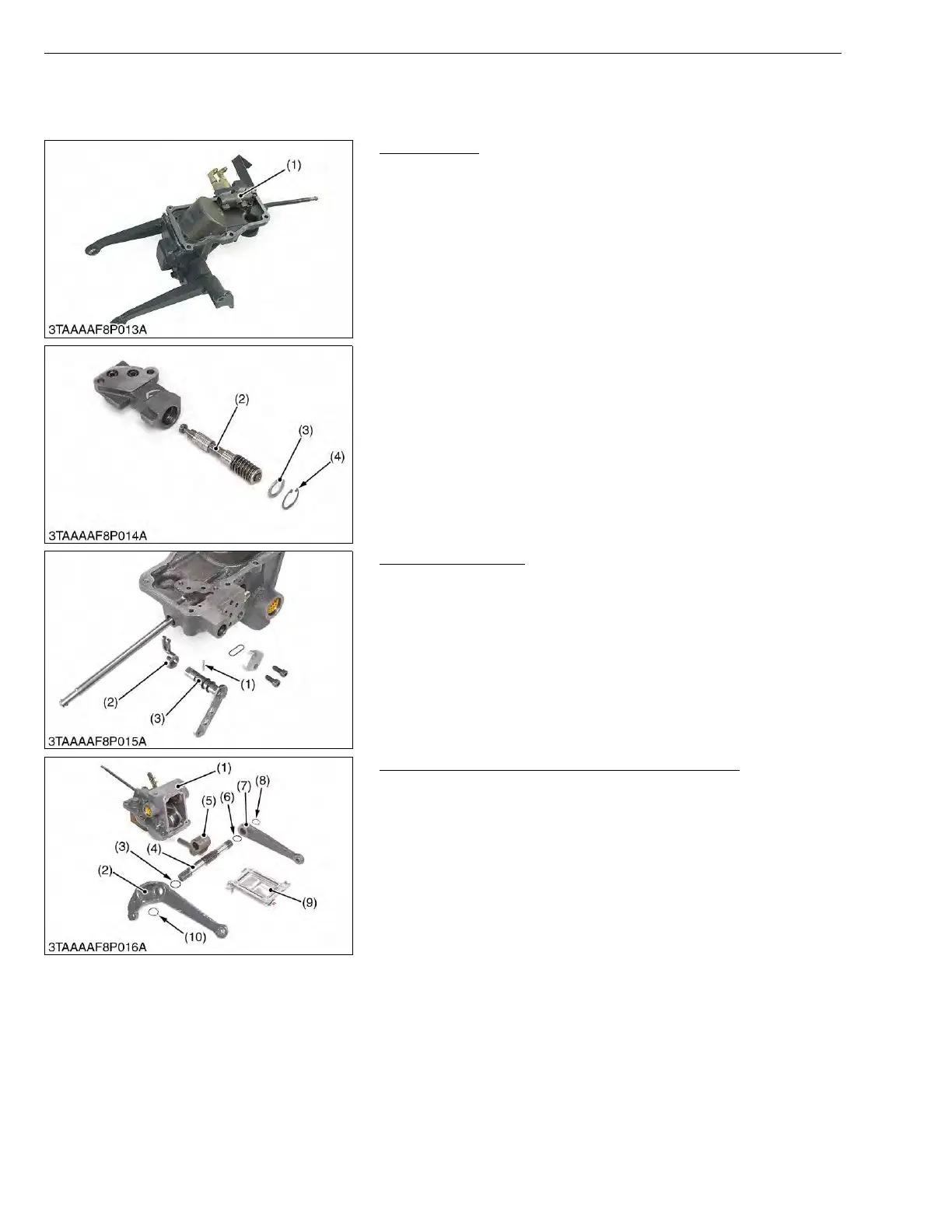
Lift Arm, Hydraulic Arm Shaft and Hydraulic Arm
1. Remove the external snap rings (8), (10), and remove the lift
arms (2), (7).
2. Draw out the hydraulic arm shaft (4).
(When reassembling)
• Align the alignment marks of the hydraulic arm (2) and hydraulic
arm shaft (4).
• Align the alignment marks of the lift arms (2), (7) and hydraulic
arm shaft (4).
• Apply grease to the right and left bushings and O-rings.
• Take care not to damage the O-ring.
W1031001
(1) Control Valve
(2) Spool
(3) Plain Washer
(4) Internal Snap Ring
(1) Pin
(2) Arm
(3) Control Valve Lever
(1) Hydraulic Cylinder Block
(2) Lift Arm LH
(3) O-ring
(4) Hydraulic Arm Shaft
(5) Hydraulic Arm
(6) O-ring
(7) Lift Arm RH
(8) External Snap Ring
(9) Cover
(10) External Snap Ring

 Loading...