6-S26
BX24, RCK54(P)-23BX, RCK60B-23BX, LA240, BT601, WSM
ELECTRICAL SYSTEM
(14) DC Outlet
DC Outlet Connector Voltage and DC Outlet Continuity
1. Disconnect the connector from the DC outlet. And turn the main
switch “ON”.
2. Measure the voltage with a voltmeter across the connector red /
blue lead and the chassis.
If the voltage differs from the battery voltage the wiring harness
is faulty.
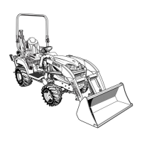
3. Disconnect the connector from the DC outlet. Since the DC
outlet can not be removed easily, measure the continuity with a
ohm meter across the plus terminal (3) and the nut (5), and
across the earth terminal (3) and the DC outlet case (6).
4. If the resistance differs from 0 ohm, the DC outlet body (1) is
faulty.
W1063447
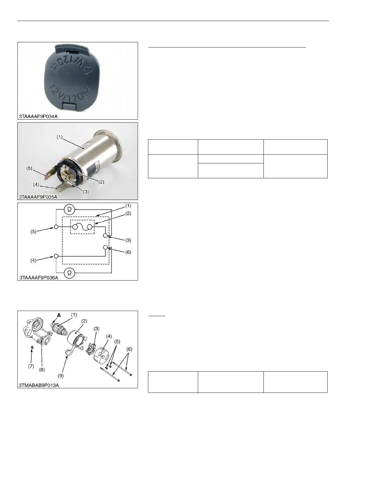
[2] DISASSEMBLING AND ASSEMBLING
(1) Starter
Motor
1. Disconnect the connecting lead (9) from the magnet switch (8).
2. Remove the screws (6), and then separate the end frame (4),
yoke (2) and armature (1).
3. Remove the two screws (5), and then take out the brush holder
(3) from the end frame (4).
(When reassembling)
• Apply grease to the spline teeth (A) of the armature (1).
W1016288
DC outlet
connector voltage
Red / Blue lead – Chassis Battery voltage
DC outlet continuity
Plus terminal – Nut
0
Earth terminal – DC outlet
case
(1) DC Outlet Body
(2) Fuse
(3) Earth Terminal (for Chassis)
(4) Plus Terminal (for Battery)
(5) Nut
(6) DC Outlet Case
Tightening torque Nut (7)
5.9 to 11.8 N·m
0.6 to 1.2 kgf·m
4.3 to 8.7 ft-lbs
(1) Armature
(2) Yoke
(3) Brush Holder
(4) End Frame
(5) Screw
(6) Screw
(7) Nut
(8) Magnet Switch
(9) Connecting Lead
A : Spline Teeth

 Loading...