6-M10
BX24, RCK54(P)-23BX, RCK60B-23BX, LA240, BT601, WSM
ELECTRICAL SYSTEM
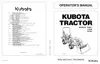
[2] IC REGULATOR (3P CONNECTOR TYPE)
3P connector is connected to the IC regulator. 3P
connector consists of three leads, Sb (Sky Blue) lead (1),
RY (Red / Yellow) lead (2), and WR (White / Red) lead
(3).
Sb (Sky Blue) lead (1) is a lead to transmit the puls
from the alternator to hour meter and tachometer. When
turning on the main switch to “ON” position, the hour
meter indicates operated hours.
While the engine runs, the tachometer indicates the
present engine revolutions.
RY (Red / Yellow) lead (2) is a lead to chassis.
WR (White / Red) lead (3) is a lead to the charge
lamp.
W1013535
(1) Sb (Sky Blue) Lead
(2) RY (Red / Yellow) Lead
(3) WR (White / Red) Lead
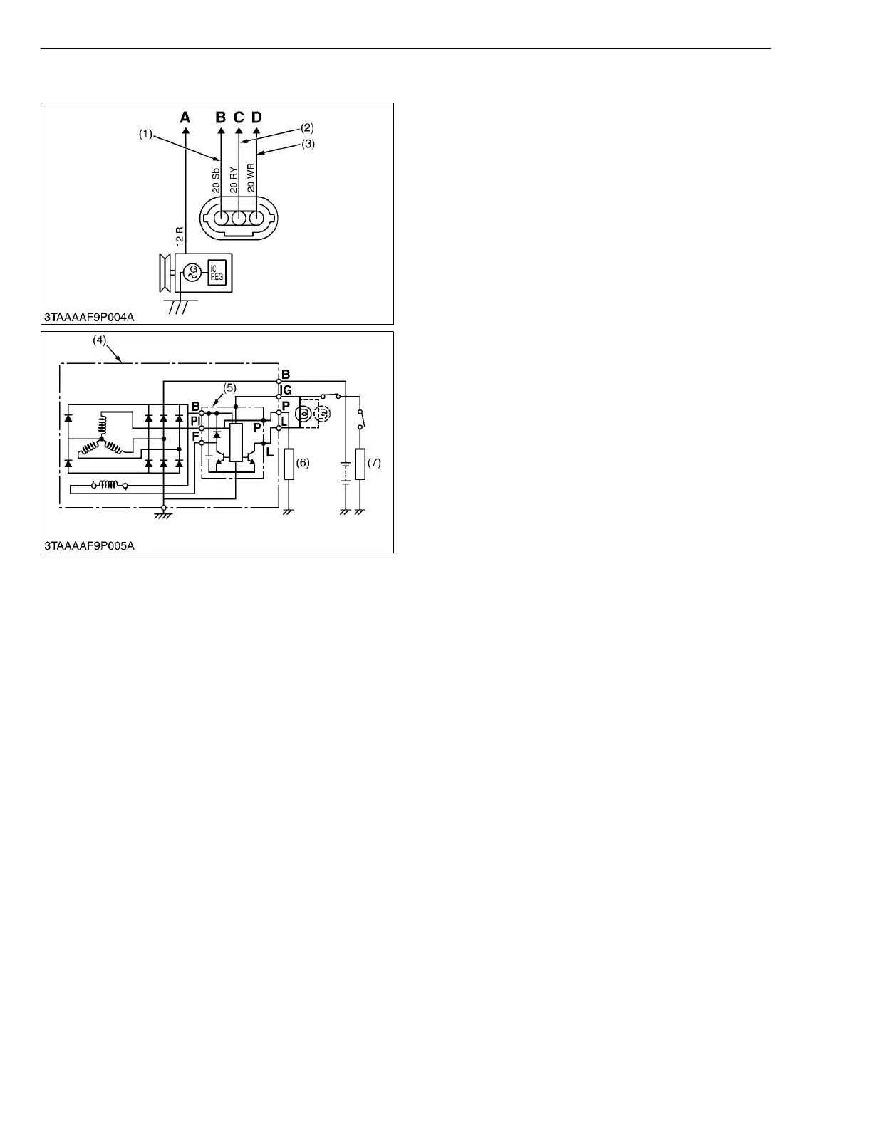
(4) Alternator Assembly
(5) IC Regulator
(6) Load
(7) Load
A : To Main Switch
B : To Hour Meter and
Tachometer
C : To Ground
D : To Charge Lamp

 Loading...