6-S10
BX24, RCK54(P)-23BX, RCK60B-23BX, LA240, BT601, WSM
ELECTRICAL SYSTEM
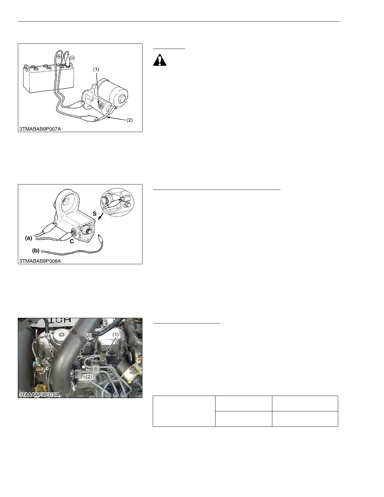
(3) Starter
Motor Test
• Secure the starter to prevent if from jumping up and down
while testing the motor.
1. Disconnect the battery negative cable from the battery.
2. Disconnect the battery positive cable and the leads from the
starter.
3. Remove the starter from the engine.
4. Disconnect the connecting lead (2) from the starter C terminal
(1).
5. Connect a jumper lead from the connecting lead (2) to the battery
positive terminal post.
6. Connect a jumper lead momentarily between the starter motor
housing and the battery negative terminal post.
7. If the motor does not run, check the motor.
W10142670
Magnet Switch Test (Pull-in, Holding Coils)
1. Remove the motor from the starter housing.
2. Preparate a 6 V battery for the test.
3. Connect jumper leads from the battery negative terminal to the
housing and the starter C terminal.
4. The plunger should be attracted and the pinion gear should pop
out when a jumper lead is connected from the battery positive
terminal to the S terminal. It’s a correct.
5. Disconnect the jumper lead to the starter C terminal. Then the
pinion gear should remain popped out. It’s a correct.
• Testing time must be 3 to 5 sec..
W1015210
(4) Glow Plug
Lead Terminal Voltage
1. Disconnect the wiring lead (2) from the glow plug (1) after turning
the main switch off.
2. Turn the main switch key to the “PREHEAT” position, and
measure the voltage between the lead terminal and the chassis.
3. Turn the main switch key to the “START” position, and measure
the voltage with a voltmeter between the lead terminal and the
chassis.
4. If the voltage at either position differs from the battery voltage, the
wiring harness or main switch is faulty.
W10149130
(1) C Terminal (2) Connecting Lead
C : C Terminal
S : S Terminal
(a) To Negative Terminal
(b) To Positive Terminal
Voltage
(Lead terminal –
Chassis)
Main switch key at
“PREHEAT”
Approx. battery voltage
Main switch key at
“START”
Approx. battery voltage
(1) Glow Plug (2) Wiring Lead (Positive)

 Loading...