1-S30
BX24, RCK54(P)-23BX, RCK60B-23BX, LA240, BT601, WSM
ENGINE
(4) Gear Case and Timing Gears
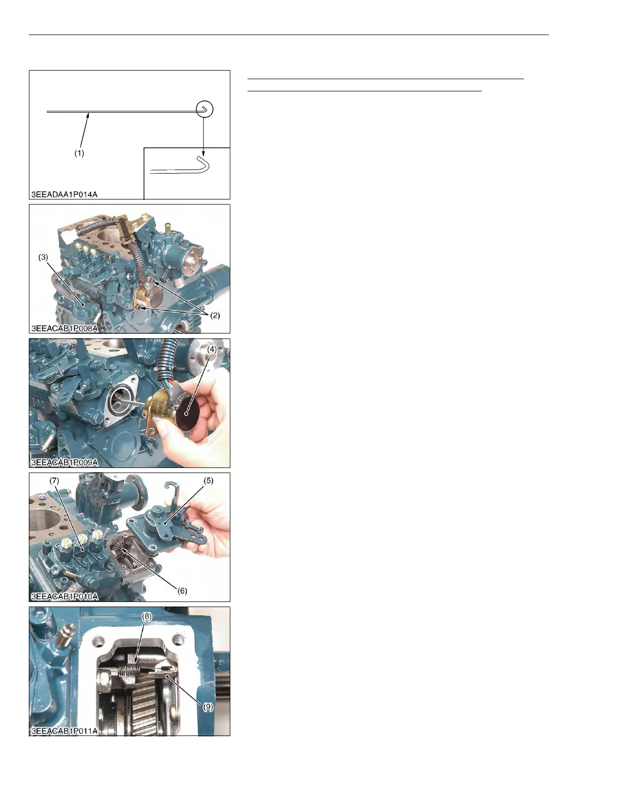
Injection Pump, Fuel Feed Pump and Speed Control Plate
(for Energize to Run Type Engine Stop Solenoid)
• Specific tool (1) :
1.2 mm diameter hard wire with its end hooked, overall
length 200 mm (7.87 in.).
The tip of wire is bent like the hook to hang governor
springs.
1. Remove the socket head screws (2), and remove the engine stop
solenoid (4).
2. Remove the screws and separate the speed control plate (5),
taking care not to damage the governor spring (6).
3. Disconnect the governor spring (6) and remove the speed control
plate (5) using the specific tool (1).
4. Remove the fuel feed pump (3).
5. Disconnect the start spring (8) from the bracket (9) using the
specific tool (1).
6. Remove the socket head screws and nuts, and remove the
injection pump (7).
W1148604
(1) Specific Tool
(2) Socket Head Screw
(3) Fuel Feed Pump
(4) Engine Stop Solenoid
(5) Speed Control Plate
(6) Governor Spring
(7) Injection Pump
(8) Start Spring
(9) Bracket

 Loading...