6-S18
BX24, RCK54(P)-23BX, RCK60B-23BX, LA240, BT601, WSM
ELECTRICAL SYSTEM
(12) Combination Switch
Combination Switch
1. Remove the meter panel, and disconnect the combination switch
connector.
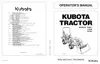
2. Remove the combination switch (1) and perform the following
checks 1) to 8).
W1049462
1) Connector Voltage
1. Connect the combination switch connector to the main wire
harness.
2. Measure the voltage with a voltmeter across the connector B1
terminal and chassis when the main switch is ON position.
3. If the voltage differs from the battery voltage, the wiring harness
and main switch is faulty.
W1050272
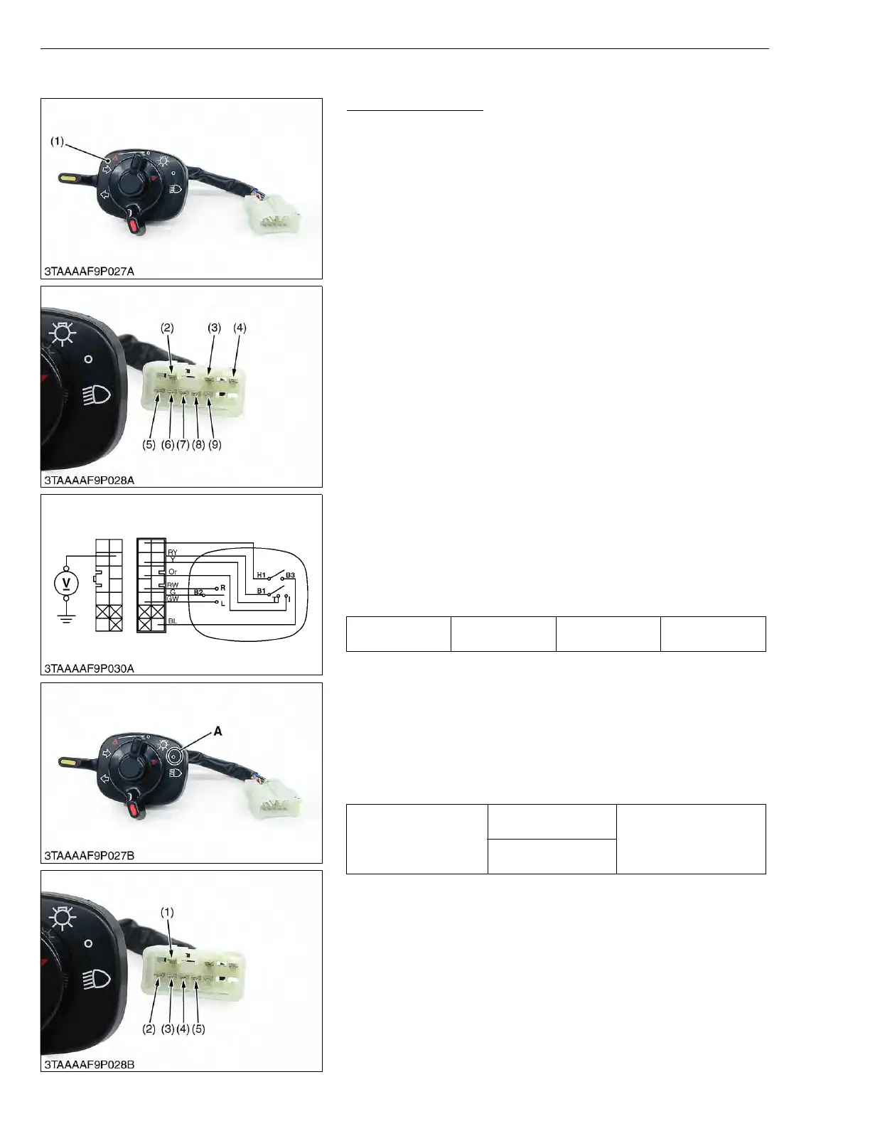
2) Head Light Switch Continuity when Setting Switch at “OFF”
Position
1. Set the light switch to the OFF position.
2. Measure the resistance with an ohmmeter across the red / yellow
lead (1) to the orange lead (4), the red / yellow lead (1) to the
yellow lead (3).
3. If infinity is not indicated, the head light switch is faulty.
W1050981
(1) Combination Switch
(2) Red / Yellow Lead
(3) Green Lead
(4) Black / Blue Lead
(5) Blue / White Lead
(6) Yellow Lead
(7) Orange Lead
(8) Red / White Lead
(9) Green / White Lead
Voltage
Main switch at
“ON” position
B1 terminal -
Chassis
Battery voltage
Resistance
(Switch at OFF position)
Red / Yellow lead (1) -
Orange lead (4)
Infinity
Red / Yellow lead (1) -
Yellow lead (3)
(1) Red / Yellow Lead
(2) Blue / White Lead
(3) Yellow Lead
(4) Orange Lead
(5) Red / White Lead
A : Head Light “OFF” Position

 Loading...