3: Installation
SLC™ 8000 Advanced Console Manager User Guide 36
Physical Installation
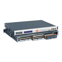
Install the SLC 8000 advanced console manager in an EIA-standard 19-inch rack (1U tall) or as a
desktop unit. The SLC module uses convection cooling to dissipate excess heat.
To install the SLC 8000 advanced console manager in a rack:
1. Place the SLC unit in a 19-inch rack.
Warning: Do not to block the air vents on the sides of the SLC module. If you
mount the SLC advanced console manager in an enclosed rack, we
recommended that the rack have a ventilation fan to provide adequate
airflow through the SLC unit.
2. Connect the serial device(s) to the SLC unit ports. See the section,
Connecting to a Device Port (on page 36).
3. Choose one of the following options:
- To configure the SLC 8000 advanced console manager using the network, or to monitor
serial devices on the network, connect at least one SLC network port to a network. See
Connecting to Network Ports (on page 39).
- To configure the SLC unit using a dumb terminal or a computer with terminal emulation,
connect the terminal or PC to the front panel SLC console port. See
Connecting Terminals (on page 39).
4. Connect the power cord, and apply power. See AC Input (on page 40).
5. Wait approximately one minute for the boot process to complete.
When the boot process ends, the SLC host name and the clock appear on the LCD display.
Now you are ready to configure the network settings as described in Chapter 4: Quick Setup.
Connecting to a Device Port
You can connect almost any device that has a serial console port to a device port on the SLC 8000
unit for remote administration. The console port must support the RS-232C interface.
Note: Many servers must either have the serial port enabled as a console or the
keyboard and mouse detached. Consult the server hardware and/or software
documentation for more information.
To connect to a serial RJ45 device port:
1. Connect one end of the Cat 5 cable to the device port.
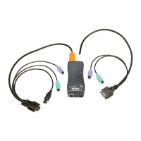
2. Connect the other end of the Cat 5 cable to an RJ45 serial console port or to other port types
using a Lantronix serial console adapter.
Notes:
See Device Port Commands to enable or disable reverse pinouts through the CLI.
Table 3-5 and Table 3-6 provide additional information on reverse pinouts.
See Appendix C: Adapters and Pinouts for information about Lantronix adapters.
3. Connect the adapter to the serial console port on the serial device as shown in Figure 3-7.
 Loading...