3: Installation
SLC™ 8000 Advanced Console Manager User Guide 38
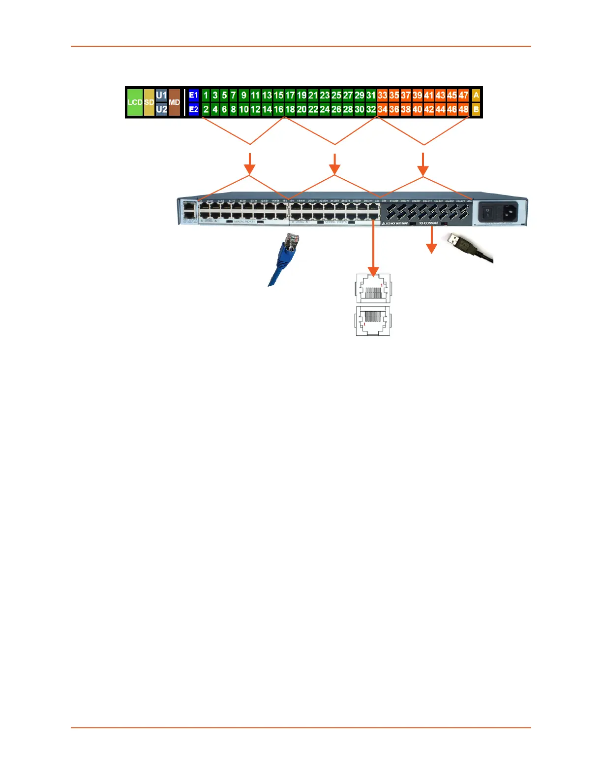
Figure 3-7 Sample Device Port Connections (Back Side)
Modular Expansion for I/O Module Bays
The SLC 8000 advanced console manager, which provides 3 separate bays, supports the
flexibility to change the I/O module configuration by offering a 16-port module for expansion. When
populating the bays, Bay 1, Bay 2 and Bay 3 must be populated in consecutive order. Bay 1 is the
slot next to the Ethernet ports and Bay 3 is the slot beside the power supply module. See
Figure 3-7 and Table 3-8. When device ports are unused or unsupported, they do not appear in
the Dashboard. See Sample Dashboards.
Note: See the SLC 8000 I/O Module Installation Guide for information on installing I/O
modules.
Bay 1 Bay 2 Bay 3
16-Port USB
I/O Module
(Part Number
FRUSB1601)
16-Port RJ45
I/O Module
(Part Number
FRRJ451601)
16-Port RJ45
I/O Module
(Part Number
FRRJ451601)
 Loading...