Home
Nordson
Industrial Equipment
VersaBlue VB Series
Nordson VersaBlue VB Series User Manual
5
of 1
of 1 rating
280 pages
Give review
Manual
Specs
To Next Page
To Next Page
To Previous Page
To Previous Page
Loading...
Maintenance
5-8
P/N 7105144G
2008 Nordson Corporation
V
ersaBlue_NW
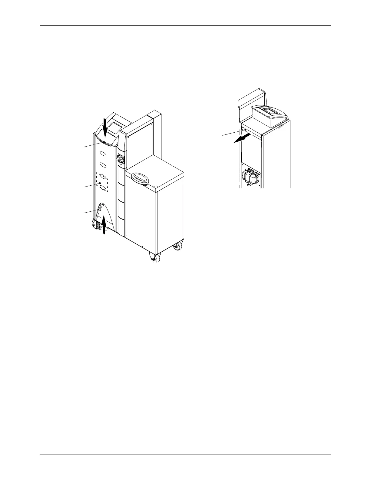
Fan and Air Filter
Depending on dust accumulation, the filters (1 and 3) for the air inlet and
outlet (4) must be cleaned (knocked out) or replaced.
1
2
3
4
Fig. 5-6
1
Air filter
, top air inlet
2 Fan
3
Air filter
, bottom air inlet
4
Air filter
, air outlet
157
159
Table of Contents
Default Chapter
3
Table of Contents
3
Nordson International
13
Europe
13
Distributors in Eastern & Southern Europe
13
Outside Europe / Hors D'europe / Fuera de Europa
14
Africa / Middle East
14
Asia / Australia / Latin America
14
Japan
14
North America
14
Safety
15
Safety Alert Symbols
15
Responsibilities of the Equipment Owner
16
Safety Information
16
Instructions, Requirements, and Standards
16
User Qualifications
17
Applicable Industry Safety Practices
18
Intended Use of the Equipment
18
Instructions and Safety Messages
18
Installation Practices
19
Operating Practices
19
Maintenance and Repair Practices
20
Equipment Safety Information
21
Equipment Shutdown
21
Relieving System Hydraulic Pressure
21
De-Energizing the System
21
Disabling the Guns
22
General Safety Warnings and Cautions
23
Other Safety Precautions
26
First Aid
26
Introduction
27
Intended Use
27
Area of Use (EMC)
27
Operating Restrictions
27
Unintended Use − Examples
28
Residual Risks
28
Series Overview
29
Note on Manual
30
Definition of Terms
30
Interface Standard I/O
30
Interface Key-To-Line Mode
30
Symbols
31
Other Sources of Information
31
Product Resource Disc
31
Melter Description
32
Illustration
32
Tank
33
Safety Valve Plate
33
Tank Isolation Valve
33
Safety Valve
33
Mechanical Pressure Control Valve
33
Pneumatic Pressure Control Valve
34
Air Relief Valve
34
Material Flow
34
Identification of Hose Connections
35
Electrical Cabinet
36
Options
37
Level Display, Level Control / Overflow Protection
37
Motor Circuit Switch
37
Pressure Display
38
Pressure Display, Box 15, Code a
38
Pressure Display and Pressure Control, Box 14, Code C
38
Pressure Build-Up, Box 14, Code N
38
ID Plate
39
Installation
41
Transport
41
Storage
41
Unpacking
41
Lifting (Unpacked Melter)
42
Installation Requirements
42
Melters with Transformer
42
Exhausting Material Vapors
42
Required Space
43
Installation Personnel's Experience
45
Screwing on Light Tower (Option)
45
Electrical Connections
46
Important Note When Using Residual Current Circuit Breakers
46
Laying Cable
46
Operating Voltage
46
External Control/Signal Circuits
46
Power Supply
47
Mains Filter
47
Installing Kit (Accessory)
47
Connecting Hose
48
Connecting Electrically
48
Connecting
48
Second Open-Jawed Wrench
48
Disconnecting
49
Relieving Pressure
49
Installing Gun
50
Filling Valve (Option)
50
Conditioning Compressed Air
50
Connecting Filling Valve
50
Key-To-Line Mode: Selecting Line Speed Voltage or Line Speed Current on the I/O Boards
51
Interface Assignment
52
Interface Standard I/O − Standard Assignment
52
General Notes
52
Interface Standard I/O − Assignment with Option Solenoid Valve Control
54
Interface Gun Solenoid Valve Control
56
Interface Key-To-Line Mode
56
One Line Speed Signal Input for All Motors
56
Separate Line Speed Signal Inputs
57
Interface Level Control
58
Pneumatic Connections
59
Pneumatic Pressure Control / Bypass Control
59
Required Air Quality
59
Setting Pressures
59
Interface Assignment Pneumatic Pressure Control
60
Interface Assignment Bypass Control
61
Inert Gas
62
Light Tower
63
Installing Kit (Accessory)
63
Casters
64
Installing Kit (Accessory)
64
Retrofitting a Temperature Control Board
65
IPC Webserver
65
Removing Melter
65
Disposing of Melter
65
Operation
67
General Information
67
Transparent Keys
67
Keys with and Without Indication Lamp
67
Meaning of Colors
67
Description of Symbols
68
Standard Symbols of Temperature Channels
68
Input Window
69
Screen Motor Controller Replacement
69
Status Display
70
Initial Startup
71
Purging Melter
71
Set on Control Panel
72
Control Panel − Overview
76
Filling the Tank
84
Manually
84
Level Display and Control (Options)
85
Automatic Tank Filling
85
Maximum Level
85
Recommended Temperature Setpoints
86
Heatup Guided by Reference Channel
87
Undertemperature Interlock
88
Motor Startup Protection
88
Acknowledge Startup Protection
88
Daily Startup
89
Daily Switchoff
90
Switching off in an Emergency
90
Control Panel of the Industrial PC (IPC)
91
Melter Modes - Overview
91
Screen Saver
92
Starting Screen
92
Temperature Parameters
93
Changing Temperature
94
Screen 1: Alarm Values
95
Graphic Presentation of Temperature Parameters
97
Monitoring of Heatup and Cooling
98
Screen 2: Activate Channel, Mode, Controlled System Heating Rate
100
Screen 3: PID Control Parameters
101
Melter
102
Entering/Exiting Standby
102
Switching On/Off All Motors (Collective Enable)
102
Switching On/Off Heaters
103
Switching On/Off Seven-Day Clock
103
Activate Password Protection
103
Alarm Log
104
Information (Melter and Control System)
105
Working with Application Groups
106
Melter Setup
111
Screen 1: Seven-Day Clock, Standby, Inert Gas
111
Changing Language, Recipes, Level
111
Screen 2: Units, Ready Delay Time, Password, Service Interval, Field Bus
117
Screen 3: Defaults, IP Address, Pressure Sensor
122
Motor
128
Switching On/Off Motor (Individual Enable)
128
Selecting Key-To-Line or Manual Mode
128
Screen 2: Key-To-Line
128
Screen 3: Motor off Delay, Threshold Switch
132
Screen 4: Pressure Alarms, Speed / Pressure Control
133
Screen 5: Pressure Build-Up, Flow Control
140
Motor Circuit Switch (Motor Maintenance Switch)
144
Operation Via the IPC Webserver
145
Setting up Connection between the Server and the Client
145
Connecting Ethernet Cable
146
Calling up Melter (Versaweb)
147
Download
147
Upload
148
Settings Record
149
Maintenance
151
Risk of Burns
151
Relieving Pressure
151
Important When Using Cleaning Agents
151
Processing Materials
152
Preventive Maintenance
152
External Cleaning
154
Control Panel
154
Visual Inspection for External Damage
155
Safety and Function Tests
155
Detaching Protective Panels
155
Detaching Insulation Blanket
155
Changing Type of Material
156
Purging with Cleaning Agent
156
Safety Valve
156
Tank
157
Draining Material
157
Cleaning Tank by Hand
157
Tightening Fixing Screws
157
Fan and Air Filter
158
Heat Exchanger
159
Cleaning
159
Performance Check
159
Replacing Fan
159
Gear Pump
160
Checking for Leakage
160
Tightening Gland
160
Pumps with Varisealtm
160
Tightening Fixing Screws
160
Motor / Gear Box
161
Changing Lubricant
161
Lubricant Selection
162
Pressure Control Valve
162
Installing Service Kit
163
Filter Cartridge
164
Replacing Filter Cartridge
164
Removing Filter Cartridge
164
Cleaning Filter Cartridge
165
Assembling Filter Cartridge
165
Installing Filter Cartridge
166
Installing Service Kit
166
Safety Valve Plate
167
Installing Service Kit
167
Tank Isolation Valve
168
Installing Service Kit
168
Safety Valve for Pneumatics
169
Performance Check
169
Cleaning
169
Pressure Sensor
170
Cleaning Separating Membrane
170
Screwing in Pressure Sensor
170
Filling Valve
171
Replacing Control Module
171
Maintenance Record Form
172
Troubleshooting
175
Helpful Tips
175
Alarm Number, Alarm Text and Optional Light Tower
176
Triggering and Resetting Alarms
180
Graphic Presentation of Temperature Parameters
180
Undertemperature and Overtemperature − Warning
181
Undertemperature Warning Triggered
181
Overtemperature Warning Triggered
181
Undertemperature and Overtemperature − Fault
182
Undertemperature Fault Triggered
182
Overtemperature Fault Triggered
182
Overtemperature − Shutdown
183
Software-Triggered
183
Shutdown by Thermostats
183
Tank Thermostat
183
Transformer Thermostat
183
Underpressure − Warning
184
Underpressure Warning Triggered
184
Overpressure − Warning − / Overpressure − Fault
185
Overpressure Warning Triggered
185
Overpressure Fault Triggered
185
Temperature Sensor − Fault
186
Short-Circuit-Triggered
186
Triggered by Broken Sensor or Open Sensor Input
186
Level (Variable Measuring Points)
186
Warning Tank Overfilled
186
Warning Tank Level Low
186
Fault Tank Empty
186
Troubleshooting (Contd.)
186
Troubleshooting Tables
188
Melter Not Functioning
188
One Channel Does Not Heat
188
Control Panel Does Not Function
189
No Material (Motor Does Not Rotate)
190
No Line Speed Signal (Voltage / Current / Frequency)
191
No Material (Motor Rotating)
192
Too Little Material or Irregular Feeding
192
Material Pressure too High
193
Material Pressure too Low
193
Incorrect Motor Rotation in Key-To-Line Mode
193
Material Residue in Tank
194
Material Hardens in Tank
194
Filling Valve (Option)
195
Others
195
I/O Board
197
Frequency Input
197
Analog Inputs
197
Digital Inputs/Outputs (Leds)
197
Leds of Temperature Control Board
200
Leds of Motor Controller
201
LED of Overflow Protection Evaluator
201
LED of Proportional Valve
201
Led's of 5-Point Sensor Evaluator
202
Leds of IPC
203
Checking Transmitted Field Bus Data
204
Repair
205
Risk of Burns
205
Observe before Performing Repairs
205
Relieving Pressure
205
Control Panel
206
Detaching Control Panel
206
Replacing Memory Board
207
Installing/Replacing the Communication Assembly
208
Please Observe
208
Replacing Motor Controller
209
Replacing CAN Module of Motor Controller
209
CAN Bus Terminating Resistor
210
On the Control Panel: Allocating Replaced
210
Motor Controllers (MC) to Their Motors
210
Replacing Pressure Sensor
212
CAN Bus Terminating Resistor
212
Procedure
212
Replacing Gear Pump
213
Tank Isolation Valve
213
Detaching Gear Pump
213
Attaching Gear Pump
214
Important Regarding Coupling
215
Replacing Motor
216
Attaching Bracket for Coupling Monitoring
217
Replacing Coupling
218
Replacing Coupling Magnets
220
Replacing Hopper Band Heater
220
Removing Old Band Heater
220
Installing New Band Heater
221
Replacing Safety Valve
222
Safety Valve
222
Safety Valve with Reed Switch
222
Installing Service Kit
223
Replacing Filter Cartridge
224
Observe When Performing Work Behind Electrical Equipment Cover
224
Replacing Thermostat
224
Replacing Temperature Sensor
225
Installing Service Kit
225
I/O Board
226
Setting ni 120 or Pt 100
227
Setting DIP Switch S3
227
Replacing Level Evaluator with Analog Sensor (Option)
228
Important Notes
228
Calibrating
229
Prerequisites
229
Replacing Level Evaluator with 5-Point Sensor (Option)
230
Important Notes
230
Calibrating
231
Prerequisites
231
Important Notes
232
Calibrating
233
Prerequisites
233
Sensor Break
233
Limit Switching Points
233
Replacing Coupler Component
234
Parts
235
How to Use Illustrated Parts List
235
Fasteners
235
Component Designation
235
Technical Data
237
General Data
237
Temperatures
238
Electrical Data
239
Max. Melter Load (Without Accessories)
240
Max. Load (Accessories)
240
Melter Types VB, VC, VW and VX
240
Melter Types VD, VE, VY and VZ
240
Melter Fuse Protection
241
Melter Types VB, VC, VW and VX
241
Melter Types VD, VE, VY and VZ
241
Mechanical Data
242
Dimensions
243
Options
245
Accessories
249
Password
251
Control Panel P/N 207023 and P/N 207850 (First Generation
255
Validity
255
Visible Distinguishing Features
255
Save Recipe
255
Troubleshooting
256
From the Communication Data List
256
Control Panel Does Not Function
257
Control Panel
257
Detaching Control Panel
258
Replacing Battery
259
Replacing Memory Board
259
Parts
260
Repair (Melter Types VB, VC, VD, VE, VW, VX, VY, VZ
262
Replacing Coprocessor Battery
262
Battery Back-Up Times
262
General Instructions Regarding Working with
263
Application Materials
263
Definition of Terms
263
Manufacturer Information
263
Liability
263
Risk of Burns
263
Vapors and Gases
264
Substrate
264
Processing Temperature
264
Glossary
265
5
Based on 1 rating
Ask a question
Give review
Questions and Answers:
Need help?
Do you have a question about the Nordson VersaBlue VB Series and is the answer not in the manual?
Ask a question
Nordson VersaBlue VB Series Specifications
General
Brand
Nordson
Model
VersaBlue VB Series
Category
Industrial Equipment
Language
English
Related product manuals
Nordson VersaBlue VA
272 pages
Nordson VersaBlue VW012
280 pages
Nordson VersaBlue VZ100
280 pages
Nordson EPC-15
2 pages
Nordson AP-300
7 pages
Nordson AltaBlue
234 pages
Nordson PURBlue EC
182 pages
Nordson DuraBlue D4L
190 pages
Nordson 3000V Series
84 pages
Nordson AD-31 Series
142 pages
Nordson DuraBlue D10L
190 pages
Nordson DuraBlue D16L
190 pages

 Loading...