EasyManuals Logo
Home>Nordson>Industrial Equipment>VersaBlue VB Series

Nordson VersaBlue VB Series User Manual

Nordson VersaBlue VB Series
280 pages
To Next Page IconTo Next Page
To Previous Page IconTo Previous Page
Page #226 background imageLoading...
Page #226 background image
3
2
1
I/O
Repair
7-22
P/N 7105144G
2008 Nordson Corporation
VersaBlue_NW
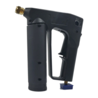
Replacing I/O Board, Temperature Control Board
NOTE: Switch / DIP switch settings, bus terminating resistors yes/no and
jumper settings are to be assumed from the replaced board.
Fig. 7-32
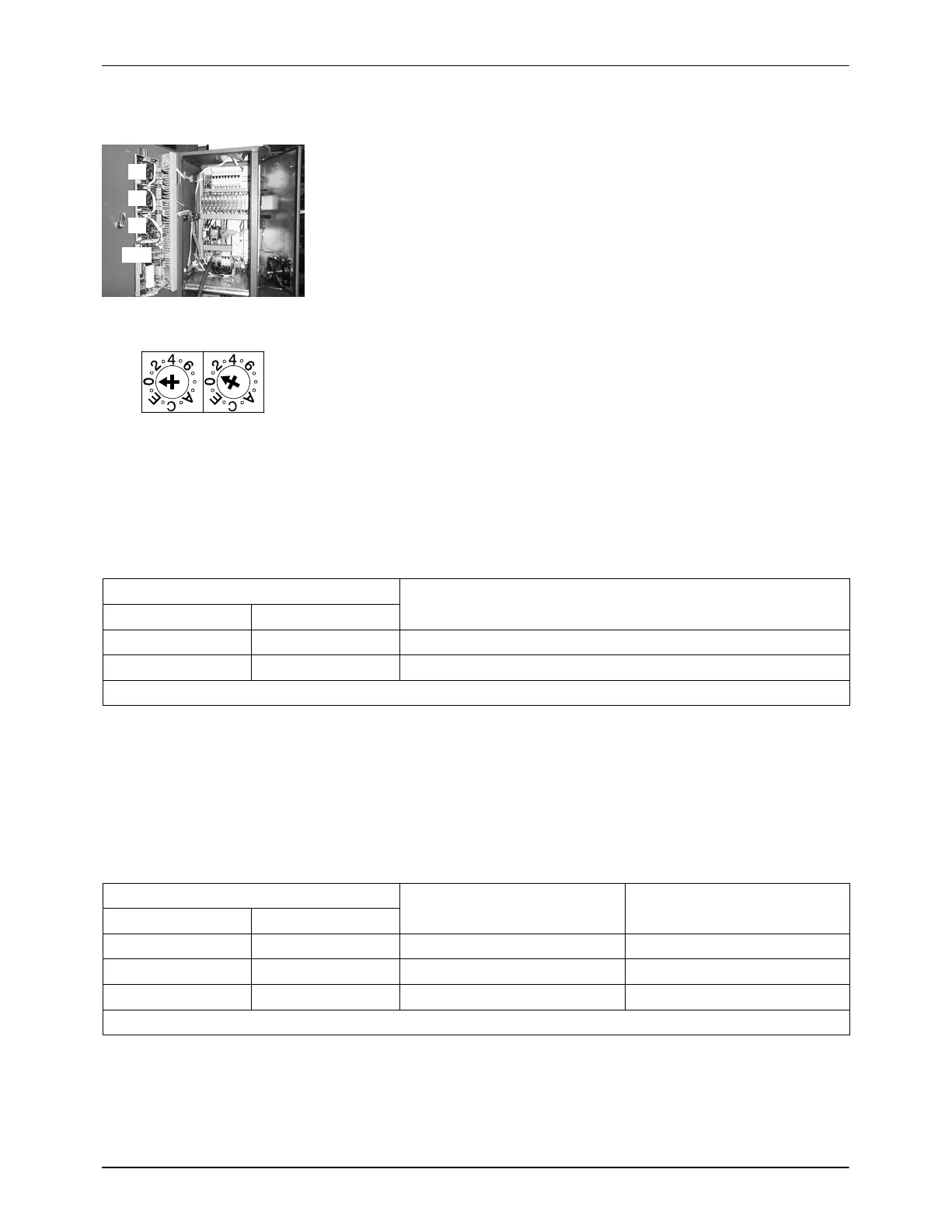
The CAN address is set on the dials using a screwdriver.
Fig. 7-33
I/O Board
Setting CAN Address
Dial (default) Board no.
SW1 SW2
0 5 1
0 6 2
NOTE: Dial setting SW1 may not be changed.
Temperature Control Board
Setting CAN Address
Dial (default) Board no. Temperature channel
S1 S2
7 1 1 1 to 6
7 2 2 7 to 12
7 3 3 13 to 18
NOTE: The switch setting S1 may not be changed.

Table of Contents

Questions and Answers:

Question and Answer IconNeed help?

Do you have a question about the Nordson VersaBlue VB Series and is the answer not in the manual?

Nordson VersaBlue VB Series Specifications

General IconGeneral
BrandNordson
ModelVersaBlue VB Series
CategoryIndustrial Equipment
LanguageEnglish

Related product manuals