Installation
3-14
P/N 7105144G
2008 Nordson Corporation
VersaBlue_NW
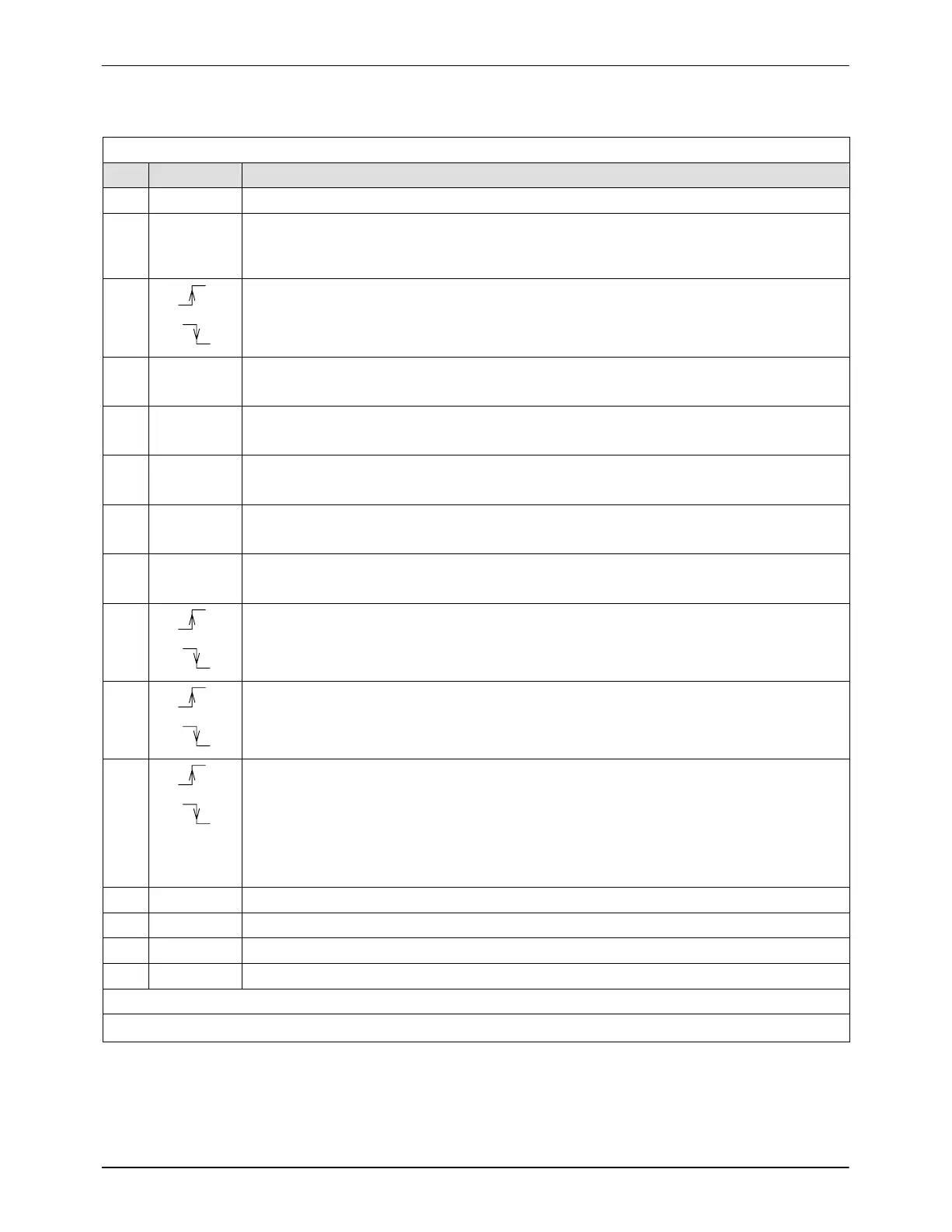
Interface Standard I/O − Assignment with Option Solenoid Valve Control
Digital inputs
Pin Input Function
1* 24 V
DC
Internal (melter)
2* 0 V
DC
External (customer’s)
NOTE: Customer connects his reference potential here, if 24 V
DC
is provided by
customer.
3
0 V
24 V
Rising edge: Heaters ON (main contactor closes)
0 V
24 V
Falling edge: Heaters OFF (main contactor opens)
4 24 V: All motors ON (collective enable)
0 V: All motors OFF
5 24 V: Enable Motor 1
0 V: No Motor 1 enable
6 24 V: Enable Motor 2
0 V: No Motor 2 enable
7 24 V: Enable Motor 3
0 V: No Motor 3 enable
8 24 V: Enable Motor 4
0 V: No Motor 4 enable
9
0 V
24 V
Rising edge: Switch on Standby
0 V
24 V
Falling edge: Switch off Standby
10
0 V
24 V
Rising edge: Key-to-line mode (for all motors)
0 V
24 V
Falling edge: Manual mode (for all motors)
11
0 V
24 V
Rising edge: Switch application group to control mode (input 1)
0 V
24 V
Falling edge: Switch application group to standby or
Falling edge: Deactivate application group
(Standby or Deactivate is dependent on the function selected on the control panel,
refer to section Operation, Working with Application Groups, Setup, Selecting Feature)
12 Like pin 11 (input 2)
13 Like pin 11 (input 3)
14 Like pin 11 (input 4)
15 Line started / stopped
Pin 16 not assigned
* selectable

 Loading...