0
Actual
Calibrate
Pressure sensors
bar
P sensor 1
Repair
7-8
P/N 7105144G
2008 Nordson Corporation
VersaBlue_NW
Replacing Pressure Sensor
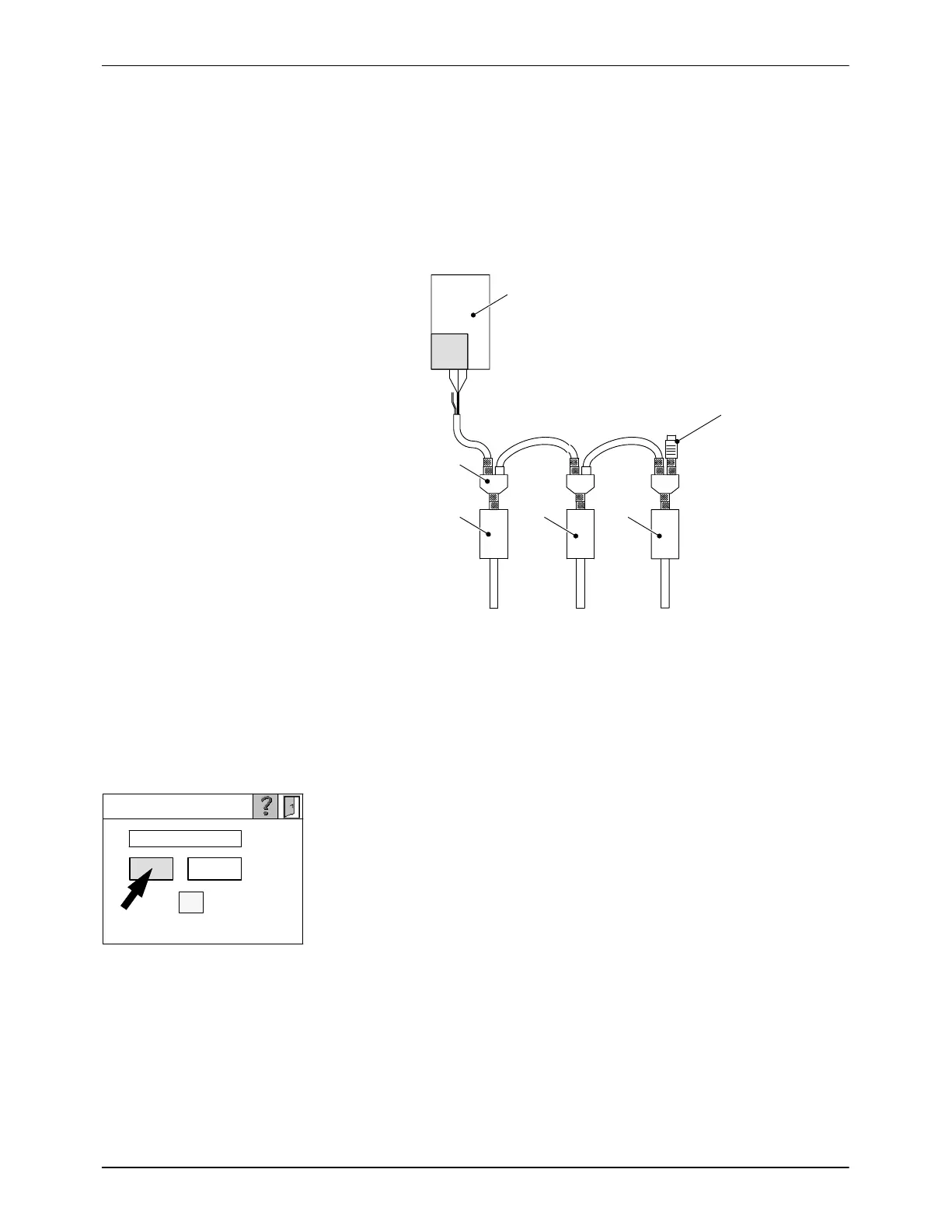
CAN Bus Terminating Resistor
The last node on the CAN bus (e.g. a pressure sensor or electrical cabinet
VBCM) must be equipped with a terminating resistor (120 W).
1
3 4
2
120 W
6
4 5
Fig. 7-12 Example with three pressure sensors
1 Motor controller
2 Connector
3 First pressure sensor
4 Second pressure sensor
5 Third pressure sensor
6 Terminating resistor
Procedure
1. Switch off the pressure sensor to be replaced (P sensor 1 in the
example). Also refer to section Operation.
2. Wait until the ON/OFF key is no longer transparent.
3. Disconnect the pressure sensor from the CAN bus.
4. Connect CAN bus cable to new pressure sensor.
5. Refer to Pressure Sensor Setup in the section Operation for information
on how to proceed.
Fig. 7-13 Example
NOTE: If during work on the CAN bus errors occur that have no readily
apparent cause (red indication lamps) or the unit shuts down, switch the
melter off then on again with the main switch.

 Loading...