1
2
3
3
4
2
4
4
3
5
Repair
7-25
P/N 7105144G
2008 Nordson Corporation
VersaBlue_NW
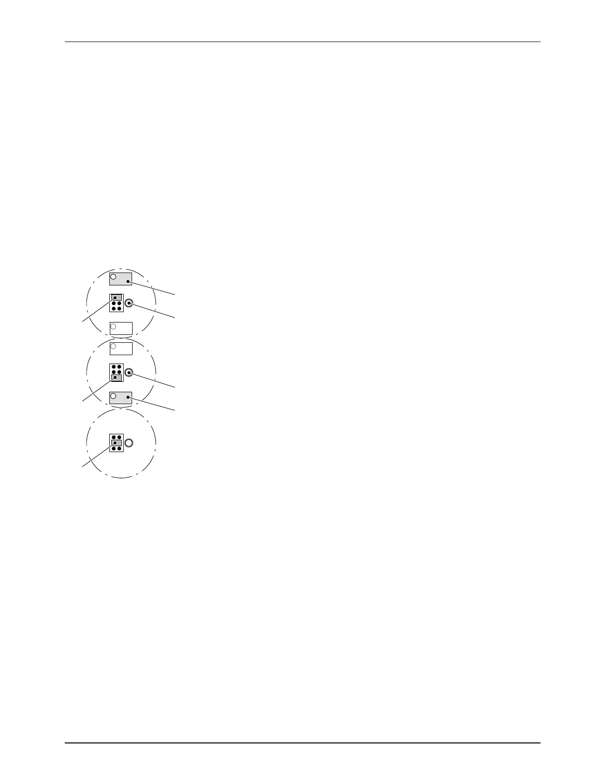
Calibrating
CAUTION: When calibrating, keep hands or conducting tools away from
coaxial connections (10, 11, Fig. 7-38) to prevent distortion of the signal.
Prerequisites
Level sensor is installed, fastened mechanically and connected
electrically (observe color of sensor cable)
Tank is empty
Level sensor is clean
Operating voltage applied (LED Operating voltage (1, Fig. 7-38) lit).
1. Plug jumper Calibration (4) into position 1.
2. With potentiometer 1 (2), find the switching point of the LED Calibration
(3) (LED just lights up).
Turn clockwise: LED on
Turn counterclockwise: LED off
3. Plug jumper Calibration (4) into position 2.
4. With potentiometer 2 (5), find the switching point of the LED Calibration
(3) (LED just lights up).
Turn clockwise: LED on
Turn counterclockwise: LED off
5. Plug jumper Calibration (4) into position 3 (center) to switch off the LED
Calibration.
Fig. 7-39
The evaluator is now ready for operation.
NOTE: The LED Reference section (9, Fig. 7-38) lights up as soon as the
reference section (area between the lower inactive section and the sensor
measuring range) is covered with material.

 Loading...