SW3
SW4
Installation
3-11
P/N 7105144G
2008 Nordson Corporation
VersaBlue_NW
Key-to-line Mode: Selecting Line Speed Voltage or Line
Speed Current on the I/O Boards
WARNING: The melter must be switched off.
CAUTION: Electrostatic charges can destroy electronic components. Wear
grounding strap!
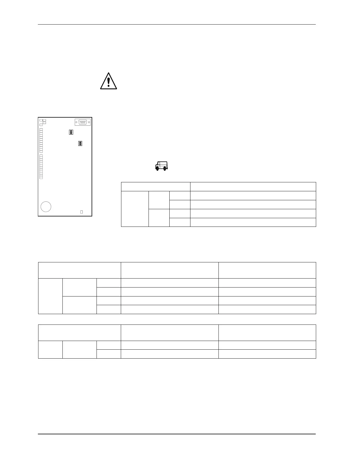
The DIP switch SW 3 on the two I/O boards can be used to choose between
two current ranges (0 to 20 mA and 4 to 20 mA).
NOTE: If the line speed signal is a frequency, these DIP switch settings
have no relevance.
The following tables indicate the original state when delivered by
Nordson (* =
). The entry ”−” in in the table means that this setting is
not permitted.
I/O Boards 1 and 2
Current range
SW3 1
ON 4 − 20 mA (*)
OFF 0 − 20 mA
2-4
ON 4 − 20 mA (*)
OFF −
Fig. 3-16 DIP switch
The DIP switches SW 4 on the two I/O boards are used to switch between
voltage and current.
I/O board no. 1
One line speed signal input for all
motors
Separate line speed signal inputs
(option)
SW4 1
ON Current −
OFF Voltage (0−10 V) (*) Voltage (0−10 V) (*)
2 to 4
ON − −
OFF Voltage (0−10 V) (*) Voltage (0−10 V) (*)
I/O board no. 2 One line speed signal input for all
motors
Separate line speed signal inputs
(option)
SW4 1 to 4
ON − −
OFF Voltage (0−10 V) (*) Voltage (0−10 V) (*)
NOTE: Voltage or current must also be set on the melter control panel.
Also refer to section Operation, step M2.1: Motor enable, Line Speed
Signal.

 Loading...