1
2
3
2
1
1
Introduction
2-7
P/N 7105144G
2008 Nordson Corporation
VersaBlue_NW
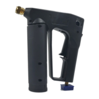
Tank
The tank is divided into grid (low melt) and reservoir (high melt) sections. An
insulating seal (2) provides a temperature barrier between the two sections.
The temperature barrier allows the material in the grid section (1) to be
gently melted at a low temperature. The material is then melted to
processing temperature in the reservoir (3).
Fig. 2-2
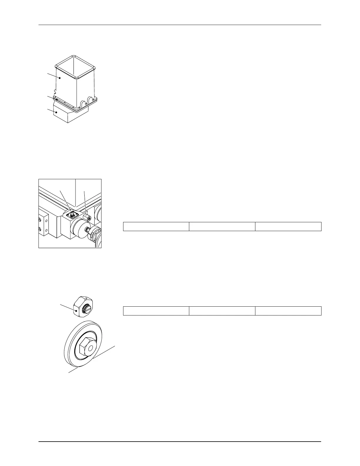
Safety Valve Plate
Tank Isolation Valve
The tank isolation valve (1) enables replacement of the gear pump without
first emptying the tank.
Safety Valve
The standard safety valve (2) is fixed at
8500 kPa
85 bar 1235 psi
When the pressure is exceeded, the safety valve opens, allowing the
material to circulate within the safety valve plate.
Fig. 2-3
Mechanical Pressure Control Valve
The mechanical pressure control valves (1) are built into the manifold above
the filter cartridge. They can be adjusted manually within the range of
500 to 9000 kPa
5 to 90 bar 72.5 to 1305 psi
One pressure control valve per pump is standardly installed after the filter
cartridge.
Fig. 2-4

 Loading...