Repair
7-11
P/N 7105144G
2008 Nordson Corporation
VersaBlue_NW
Important Regarding Coupling
1 1 1 1
=
=
2
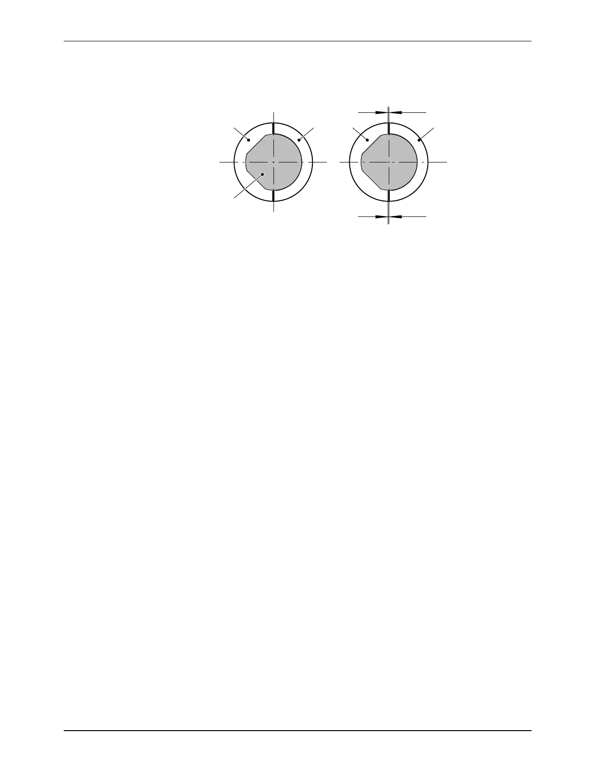
Fig. 7-19
Turn the coupling half shells (1) such that the diagonal surfaces of the
pump shaft (2) rest on those of the coupling half shells (Refer to
Fig. 7-19).
The coupling half shells must be tightened such that the gaps are the
same size (Refer to Fig. 7-19).
Extract from manufacturer’s installation and operating instructions:
The drive shaft and output shaft should be parallel* to one another. If the
axes lean towards one another, excess load is applied to the edges of
the bearings, causing premature wear.
The coupling may not be twisted axially. Intermediate disk should move
freely.
The coupling should not be disassembled. Interchanging of coupling
links and disks, damaged sealing rings, polluted bearings, etc. can
cause premature malfunctioning.
All three coupling disks must be aligned to the dimension** of the shaft
offset. If the intermediate disk is extremely off-center − meaning that the
coupling links are no longer parallel − the coupling may be destroyed
upon startup.
* = axially aligned
** = within the permitted shaft offset

 Loading...