Introduction
2-12
P/N 7105144G
2008 Nordson Corporation
VersaBlue_NW
Options (contd.)
Pressure Display
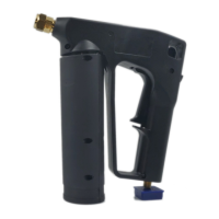
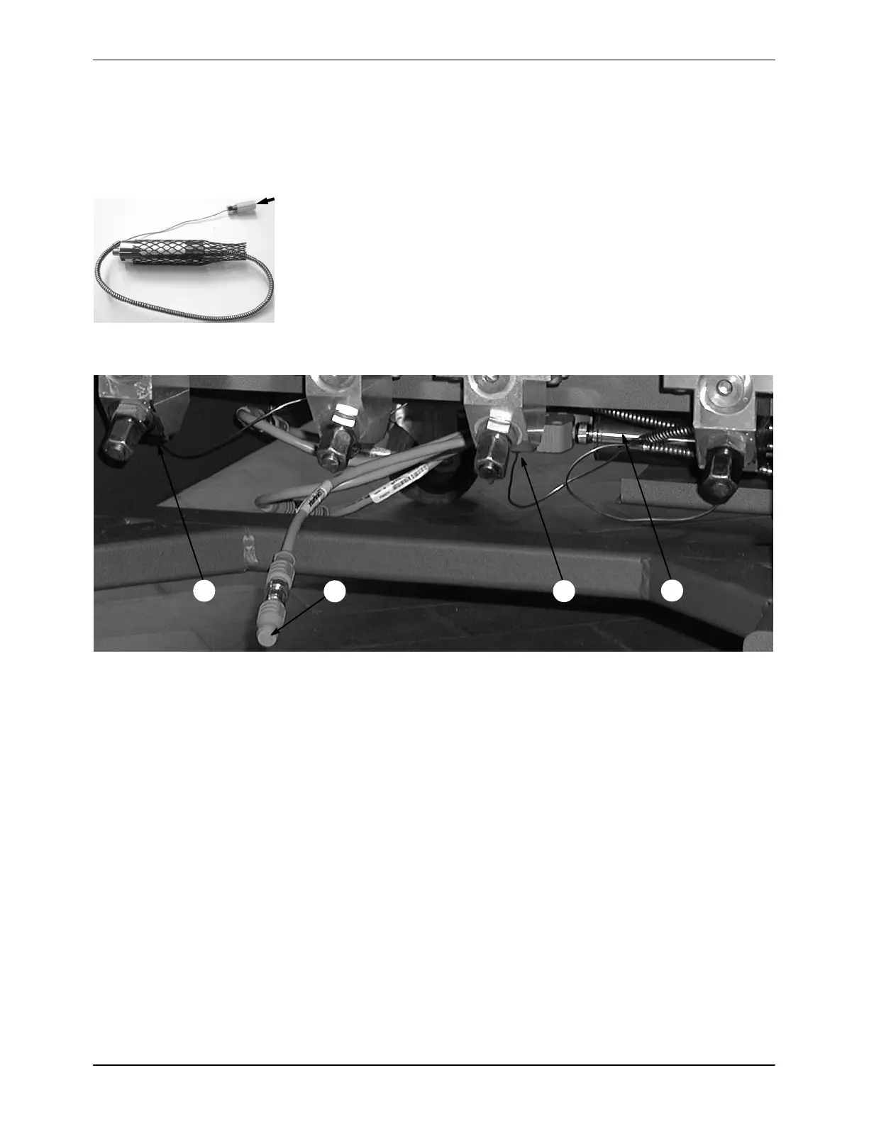
The pressure sensors (Fig. 2-11 and 1, Fig. 2-12) for material outlet
pressure are located in the hose connections. The corresponding
measuring transducers (2) are located below the manifold. The last
pressure sensor along the bus must be equipped with a terminating
resistor (3).
Fig. 2-11
1
1
2
3
Fig. 2-12 Pressure sensors in the hose connections (right side of melter, refer to Fig. 2-1)
Pressure Display, Box 15, Code A
Each pump stream is equipped with a pressure sensor for the pressure
display in systems with only double-stream pumps and in systems with both
single-stream and double-stream pumps.
Pressure Display and Pressure Control, Box 14, Code C
Pressure Build-up, Box 14, Code N
The single-stream pump is equipped with a pressure sensor for the
pressure display and control in systems with both single-stream and
double-stream pumps. In the double-stream pump each pump stream is
equipped with a pressure sensor for the pressure display. However, only
one each is used for pressure control.
In systems consisting only of double-stream pumps, each pump is equipped
with two pressure sensors for the pressure display. However, only one each
is used for pressure control.

 Loading...