ON
4 − 20 mA
ON
0 − 10 V
1 2345678
ON
OFF
ON
ON
ON
OFF
OFF
OFF
ON
OFF
ON
ON
ON
OFF
OFF
OFF
Installation
3-20
P/N 7105144G
2008 Nordson Corporation
VersaBlue_NW
Pneumatic Connections (contd.)
Pneumatic Pressure Control / Bypass Control (contd.)
Interface Assignment Pneumatic Pressure Control
PIN Input Function
1 −
4 − 20 mA
0 − 10 V
Proportional valve pump 1
2 +
3 −
4 − 20 mA
0 − 10 V
Proportional valve pump 2
4 +
5 −
4 − 20 mA
0 − 10 V
Proportional valve pump 3
6 +
7 −
4 − 20 mA
0 − 10 V
Proportional valve pump 4
8 +
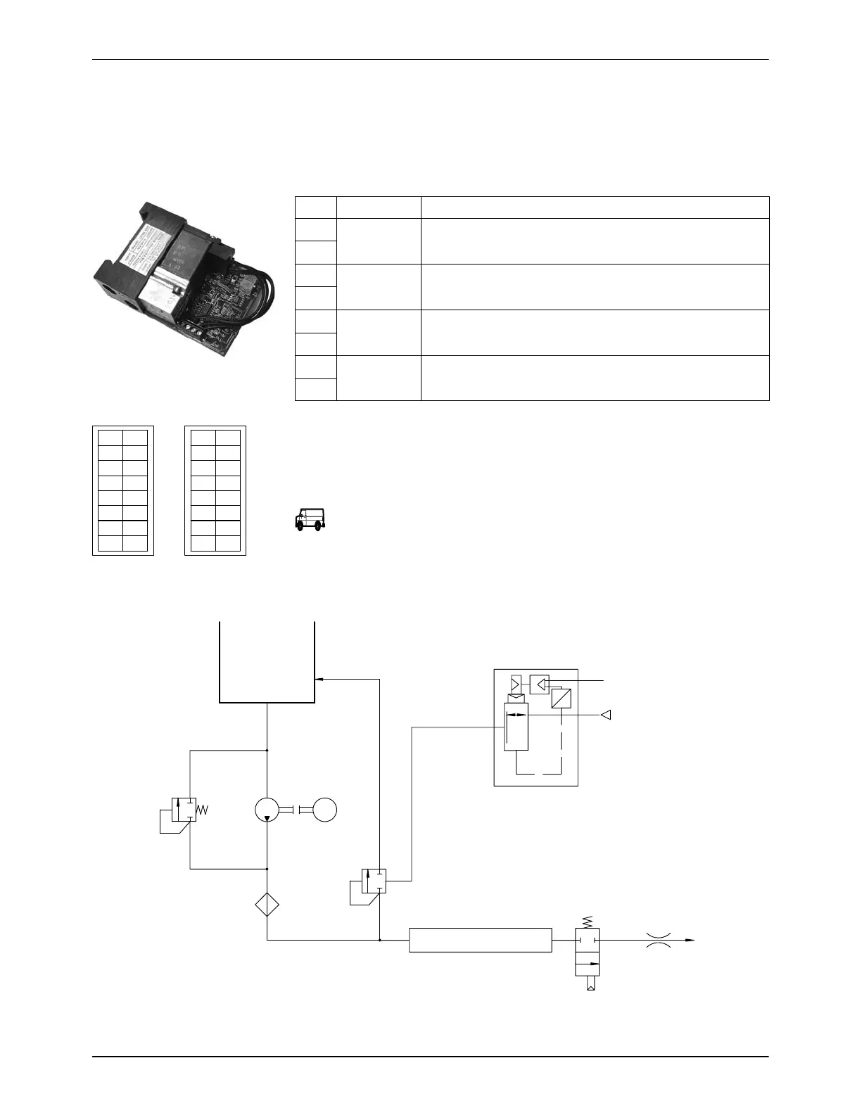
The proportional valves for pneumatic pressure control are located in the
melter tower. The DIP switch SW 1 is on the back of the printed circuit
board.
DIP switch SW1 to switch between 0 − 10 V and 4 − 20 mA.
0 − 10 V
Fig. 3-22 SW1
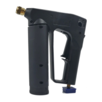
Compressed air
Proportional valve
NozzleGun
Hose
Pneumatic pressure
control valve
MotorPump
Filter
Tank
M
0−10 V or
4−20 mA
Fig. 3-23 Option Pneumatic pressure control (1 pump)

 Loading...