Introduction
2-10
P/N 7105144G
2008 Nordson Corporation
VersaBlue_NW
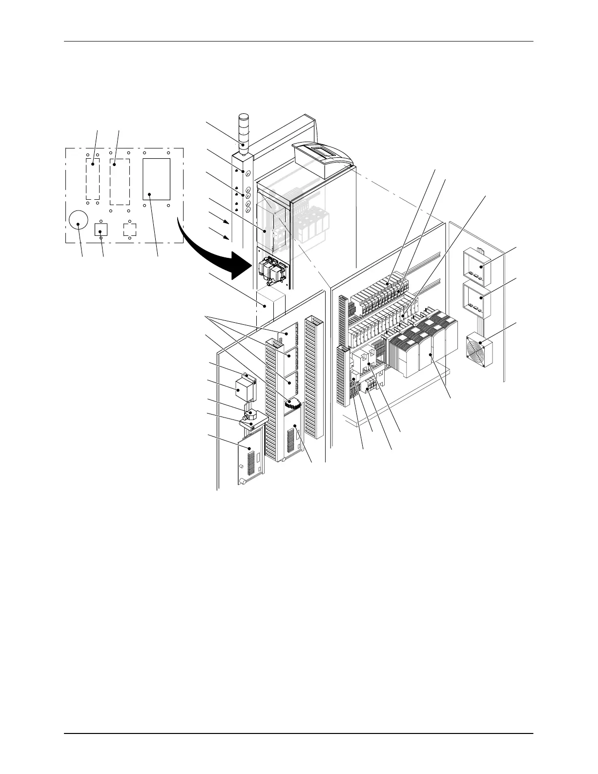
Electrical Cabinet
5
4
3
21
16
17
23
12
18
10
8
6
14
19
22
21
20
9
7
15
13
11
31
24
28
29
27
26
25
30
Interface assignment
Fig. 2-9
1 Interface Level control (option),
XS 3
2 Cable duct PROFIBUS (option),
XS D
3 Cable gland Power supply
4 Interface Key-to-line, XS 5
5 Interface Standard I/O, XS 2
6 Mains filter (accessory)
7 Interfaces Line speed signal
inputs (XS 5.1 to XS 5.4)
8 Interface Pneumatic pressure
control / bypass control (option),
XS 4
9 Heat exchanger, (option)
10 Pressure displays Pneumatic
bypass (option)
11 Pressure display Inert gas
(option)
12 Light tower (accessory/option)
13 Circuit breakers (for
3 x 200 V
DC
and 3 x 230 V
DC
)
14 Circuit breakers (for
3 x 400 V
DC,
3 x 400 V
DC
+ N
and 3 x 480 V
DC
)
15 Solid state relay
16 Evaluator Level control (option)
17 Evaluator Separate overflow
protection (option)
18 Fan (not present with heat
exchanger)
19 Motor controller
20 Power supply 24 V
DC
21 Circuit breaker Main fuse
22 Main contactor
23 Mains terminals
24 I/O board 1
25 I/O board 2
26 Gateway (option)
27 ControlNet tap (option)
28 Coprocessor (option)
29 Ethernet switch (option)
30 Transformer module
31 Temperature control board

 Loading...