1 + 24 V
DC
2 0 V
DC
+24 V
DC
0 V
DC
100 kHz
3 f
in
1 A
gnd
2 + A1
in
+24 V
DC
0 V
DC
+ 24 V
DC
0 V
DC
+ 24 V
DC
0 V
DC
+ A2
in
+ 24 V
DC
0 V
DC
+ A3
in
+ 24 V
DC
0 V
DC
+ A4
in
1
2
3
4
5
6
7
A1
A12
E1
E12
Troubleshooting
6-23
P/N 7105144G
2008 Nordson Corporation
VersaBlue_NW
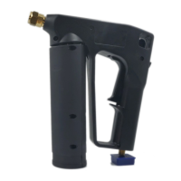
I/O Board
Frequency Input
X14.3 One line speed signal for all motors (I/O board #1)
Analog Inputs
X4.2 One line speed signal for all motors (I/O board #1)
X5.3 Level sensor (I/O board #1)
X10 Line speed signal for motor 1 (I/O board #1)
X10 Line speed signal for motor 3 (I/O board #2)
X15 Line speed signal for motor 2 (I/O board #1)
X15 Line speed signal for motor 4 (I/O board #2)
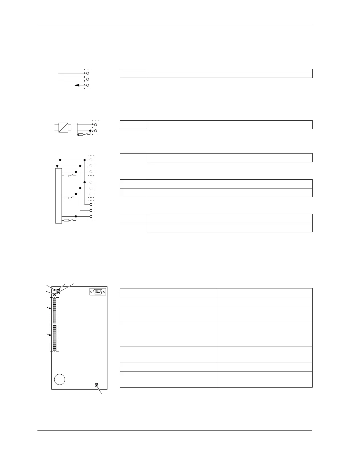
Digital Inputs/Outputs (LEDs)
Digital outputs LEDs (1) Lit for active output
Digital inputs LEDs (2) Lit for active input
FIN LED (3) Lights as soon as pulses > 1 Hz at
frequency input
RUN LED (4) Lit when power is ON (melter
switched on)
Flashing during operation
CAN communication (5) Lights up as soon as
communication occurs at CAN bus
CAN error (6) Lit with communication fault
Fuse (7) Lit when 24 V
DC
supply to internal
outlets OK

 Loading...