134 Rockwell Automation Publication 2198-UM005C-EN-P - February 2022
Chapter 6 Configure and Start up the Kinetix 5300 Drive System
Configure Axis Properties
In this section you configure the axis properties of your Kinetix 5300 servo
drive for the type of feedback that you intend to use in your application.
Table 64 - Valid Feedback Assignments
Digital AqB (TTL) Feedback
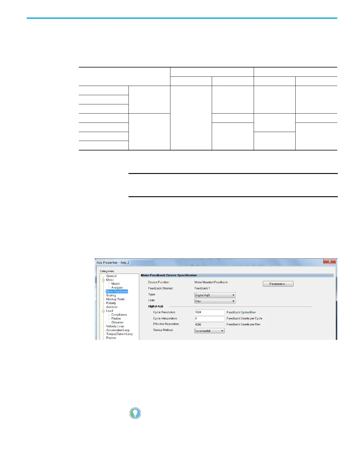
In this example, a motor feedback device is configured for Digital AqB
feedback.
1. In the Controller Organizer, right-click an axis and choose Properties.
2. Select the Motor Feedback category.
The Motor Feedback Device Specification dialog box appears.
3. Configure the device function and type.
In this example, Motor Feedback is the device function and Digital AqB is
the feedback type.
4. Enter values for the Digital AqB specification fields.
The only valid value for Cycle Interpolation is 4.
5. From the Startup Method pull-down menu, choose Incremental.
6. Click Apply.
Feedback Type
Permanent Magnet Motors Induction Motors
Motor Feedback Load Feedback Motor Feedback Load Feedback
Hiperface
(1)
High-resolution
single-turn and multi-
turn, absolute
Supported
–––
Nikon
(1)
Tamagawa
(1)
Digital AqB
(2)
Incremental
Supported
Supported
Supported
Digital AqB with UVW
(2)
––
Sine/Cosine
(2)
–
Sine/Cosine with UVW
(2)
(1) This feedback option is automatically configured via the motor catalog number.
(2) See the sections that follow for the respective information to configure this feedback type.
IMPORTANT The examples below are applicable when the motor Data Source is the
Nameplate Datasheet. When selecting a motor via the Catalog Number,
the appropriate fields are automatically populated.
When the Device Function is Load-Side Feedback or Master Feedback,
configuration is identical to Motor Mounted Feedback.

 Loading...


