Rockwell Automation Publication 2198-UM005C-EN-P - February 2022 63
Chapter 4 Connector Data and Feature Descriptions
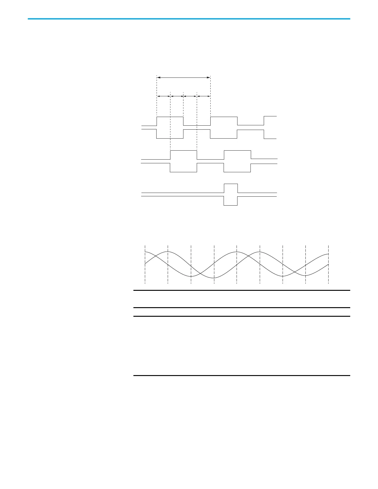
Encoder Phasing Definitions
For TTL encoders, the drive position increases when A leads B. Clockwise
motor rotation is assumed, when looking at the shaft.
Figure 30 - TTL Encoder Phasing
For Sin/Cos encoders, for example Hiperface, the drive position increases
when Cosine (B) leads Sine (A). Clockwise motor rotation is assumed, when
looking at the shaft.
Figure 31 - Sine/Cosine Encoder Phasing
A
/A
90°
90°
90° 90°
360°
B
/B
Z
/Z
IMPORTANT The Sine/Cosine encoder signal phasing is different than the TTL encoder
signal phasing.
IMPORTANT When using an incremental Sine/Cosine feedback device, the drive
cannot synthesize a marker signal, so a physical marker signal is
required for the home-to-marker sequence (and the marker hookup
test) to complete.
When using absolute feedback devices (for example, Hiperface) the drive
synthesizes a marker signal because these devices don't have a marker
signal required for the home-to-marker sequence (and the marker
hookup test) to complete.

 Loading...


