Rockwell Automation Publication 2198-UM005C-EN-P - February 2022 217
Appendix C Motor Control Feature Support
The Dynamic test requires that the Positive and Negative Torque Limits for
said axis are not over-written while the test is in progress. This can be satisfied
by making sure that (1) these cyclic attributes are not checked as writable
within the Drive Parameters tab of the axis properties and (2) these
parameters are not being messaged via an MSG instruction.
When configured for closed-loop control, the Dynamic test requires that an
accurate system inertia is set in the Logix Designer application.
• For the Logix Designer application, version 29.00 or later, a default value
is automatically populated by the controller.
• For the Logix Designer application, version 28.00 or earlier, this can be
done by running and accepting the results of an Autotune test, or by
entering the motor inertia value directly into the Logix Designer
application.
When configured for closed-loop control, the Dynamic test uses the velocity
regulator tuning as entered into the Logix Designer application. If the motor is
coupled to a load, the velocity regulator tuning may need to be adjusted to
make sure the velocity response is well controlled. The Dynamic test fails if the
steady-state velocity feedback is not within a ±30% tolerance of the
commanded velocity.
If using the Dynamic test in Frequency Control mode, uncouple the motor
from any load or results may not be valid. In closed-loop control, either a
coupled or uncoupled load produces valid results.
Selection of Motor Thermal
Models
The Kinetix 5300 drives contain two motor thermal-overload protection
algorithms that you can use to prevent the motor from overheating.
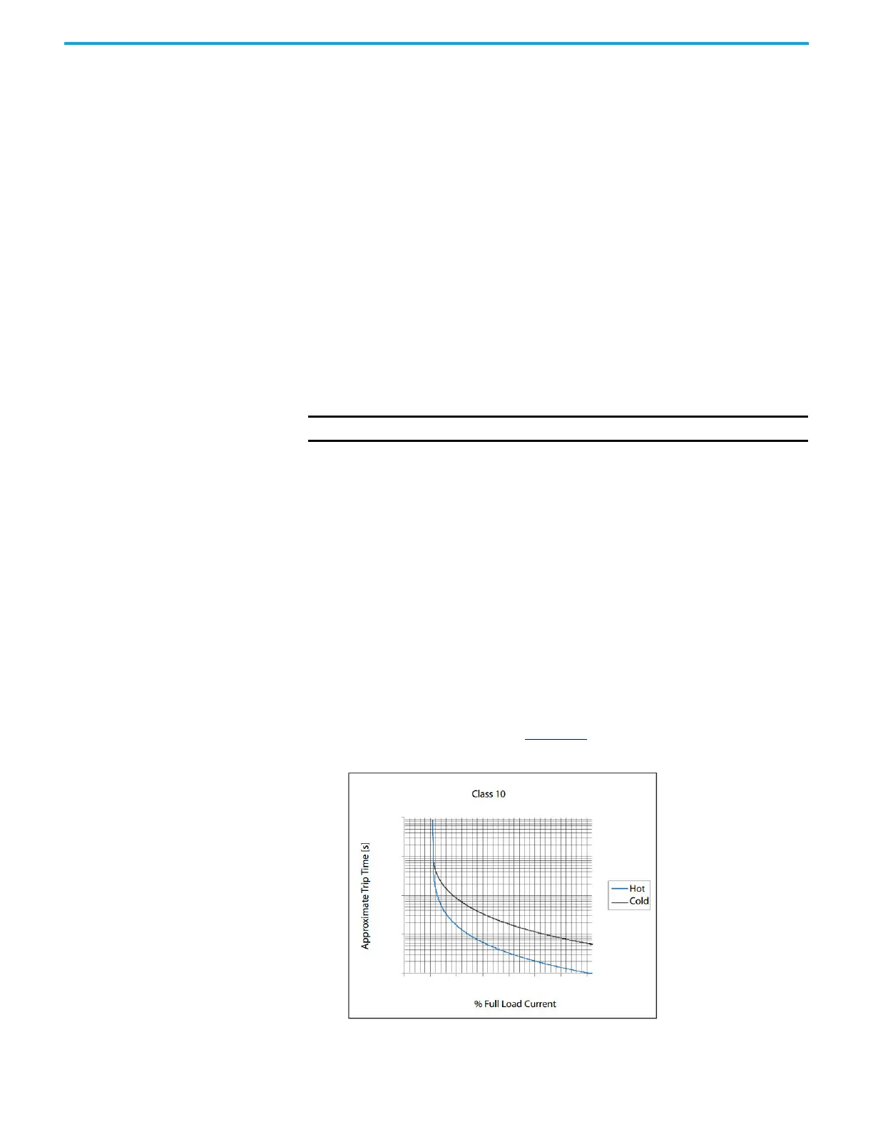
Generic Motors
The default thermal model is a generic I
2
T Class 10 overload protection
algorithm. This model is active if the MotorWindingToAmbientResistance or
the MotorWindingToAmbientCapacitance values are 0.0. The purpose of this
algorithm is to limit the time a motor is operating with excessive levels of
current. The relationship between Motor Overload Factory Limit trip-time and
motor output current is shown in Figure 113
.
Figure 113 - Motor Overload Curve
IMPORTANT The Dynamic test is not supported in closed-loop Torque Control.
10
100
1000
10,000
100,000
100
125
150
175
200
225
250
0

 Loading...


