78 Rockwell Automation Publication 2198-UM005C-EN-P - February 2022
Chapter 5 Connect the Kinetix 5300 Drive System
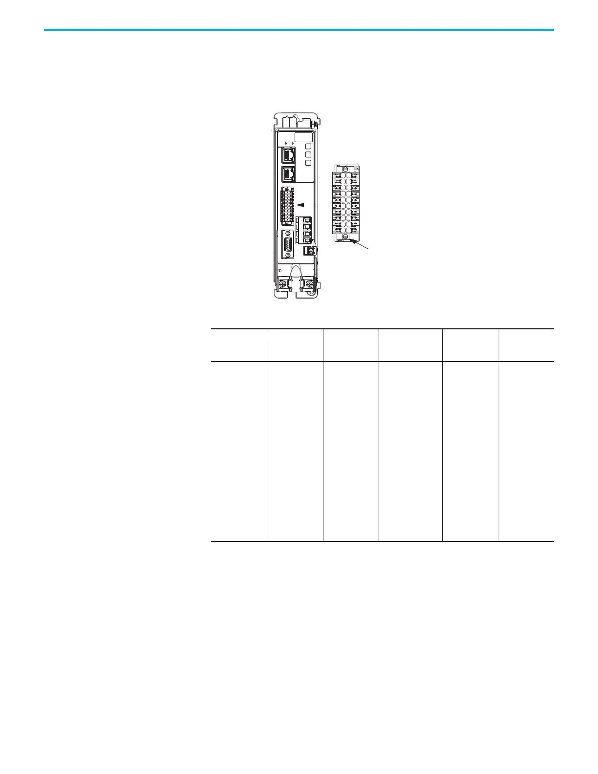
Wire the Digital Inputs and Auxiliary Feedback Connector
The digital inputs and auxiliary feedback connector uses spring tension to hold
wires in place.
Figure 41 - Digital Inputs and Auxiliary Feedback Connector Wiring
Table 39 - Digital Inputs and Auxiliary Feedback Connector Specifications
Digital Inputs and Auxiliary Feedback
Connector Plug
Kinetix 5300 Servo Drive
(front view)
The digital inputs and auxiliary feedback connector
plug includes two mounting screws.
Torque screws 0.22 N•m (2.0 lb•in).
Drive Cat. No. Pin Signal
Recommended
Wire Size
mm
2
(AWG)
Strip Length
mm (in.)
Torque Value
N•m (lb•in)
2198-Cxxxx-ERS
1
2
3
4
5
6
7
8
9
10
11
12
13
14
15
16
17
18
19
20
IN1
COM
IN2
COM
SHIELD
AUX_AM+
AUX_BM+
AUX_IM+
AUX_EPWR_5V
SHIELD
IN3
COM
IN4
COM
SHIELD
AUX_AM-
AUX_BM-
AUX_IM-
AUX_COM
SHIELD
0.2…1.5
(24…16)
10.0 (0.39)
—
(1)
(1) This connector uses spring tension to hold wires in place.

 Loading...


