Rockwell Automation Publication 2198-UM005C-EN-P - February 2022 33
Chapter 2 Plan the Kinetix 5300 Drive System Installation
Minimum Clearance Requirements
This section provides information to assist you in sizing your cabinet and
positioning your Kinetix 5300 drive:
• Additional clearance is required for cables and wires or the 24V DC
shared-bus connection system connected to the top of the drive.
• Additional clearance is required if other devices are installed above and/
or below the drive and have clearance requirements of their own.
• Additional clearance left and right of the drive is required when mounted
adjacent to noise sensitive equipment or clean wire ways.
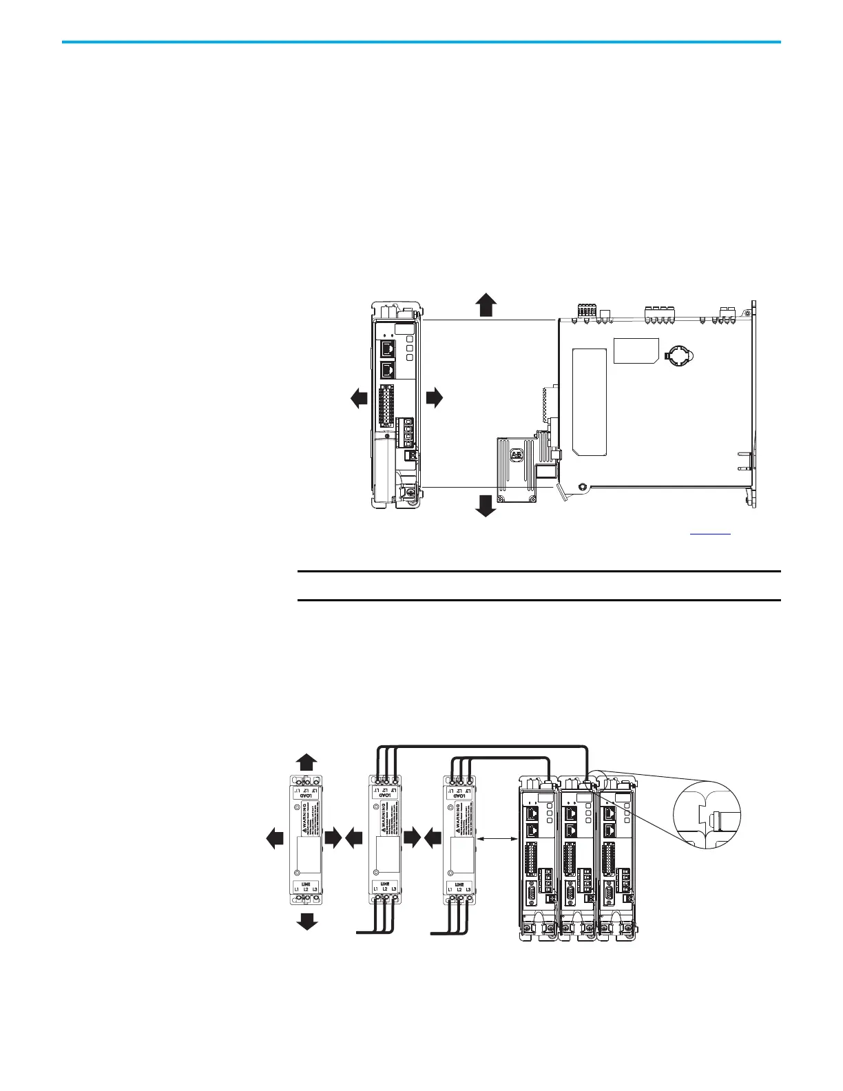
Figure 10 - Minimum Clearance Requirements
In 24V shared-bus configurations (optional), drives must be spaced by aligning
the zero-stack tab and cutout. Install the AC line filter (required for CE) with
50 mm (1.97 in.) minimum clearance between the drive and filter or between
filters, when more than one filter is used. Minimize the cable length as much
as possible.
Figure 11 - 24V Shared-bus and Line Filter Clearance Requirements
(1) Clearance required at the terminals for NEC specified bend radius depends on the wire size in use.
Clearance right of the
drive is not required.
Clearance left of the
drive is not required.
Kinetix 5300
Servo Drive
40 mm (1.57 in.) clearance below
drive for airflow and installation.
40 mm (1.57 in.) clearance above
drive for airflow and installation.
Refer to the Kinetix 5700, 5500, 5300,
and 5100 Servo Drives Specifications
Technical Data, publication KNX-TD003
,
for Kinetix 5300 drive dimensions.
IMPORTANT Mount the drive in an upright position as shown to provide proper air flow.
MBRK
W
V
U
1
10
1
2
MFB
MBRK
W
V
U
1
10
1
2
MFB
MBRK
W
V
U
1
10
1
2
MFB
50 mm
(1.97 in.)
50 mm
(1.97 in.)
50 mm
(1.97 in.)
50 mm
(1.97 in.)
Zero-stack Tab and
Cutout Aligned
The 24V shared-bus system
is not shown for clarity.
Wire Connection
(1)
Te rm in al s
Wire Connection
(1)
Ter mi na ls
Minimize Cable Length from Filter to Drive

 Loading...


