EasyManuals Logo
Home>Rockwell Automation>Servo Drives>Allen-Bradley Kinetix 5300

Rockwell Automation Allen-Bradley Kinetix 5300 User Manual

Rockwell Automation Allen-Bradley Kinetix 5300
246 pages
To Next Page IconTo Next Page
To Previous Page IconTo Previous Page
Page #53 background imageLoading...
Page #53 background image
Rockwell Automation Publication 2198-UM005C-EN-P - February 2022 53
Chapter 4 Connector Data and Feature Descriptions
Input Power Connector Pinouts
Table 13 - AC Input Power Connector
Table 14 - 24V DC Input Power Connector
Shunt Resistor Connector Pinouts
Table 15 - Shunt Resistor Connector
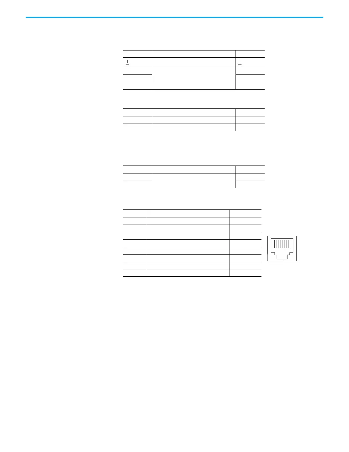
Ethernet Communication Connector Pinout
Pin Description Signal
Chassis ground
L3
Three-phase input power
L3
L2 L2
L1 L1
Pin Description Signal
1 24V power supply, customer supplied 24V+
2 24V common 24V-
Pin Description Signal
Shunt connections
DC+
–SH
Pin Description Signal
1Transmit+ TD+
2Transmit- TD-
3 Receive+ RD+
4 Reserved
5 Reserved
6 Receive- RD-
7 Reserved
8 Reserved
1
8

Table of Contents

Other manuals for Rockwell Automation Allen-Bradley Kinetix 5300

Questions and Answers:

Question and Answer IconNeed help?

Do you have a question about the Rockwell Automation Allen-Bradley Kinetix 5300 and is the answer not in the manual?

Rockwell Automation Allen-Bradley Kinetix 5300 Specifications

General IconGeneral
BrandRockwell Automation
ModelAllen-Bradley Kinetix 5300
CategoryServo Drives
LanguageEnglish

Related product manuals