Rockwell Automation Publication 2198-UM005C-EN-P - February 2022 173
Appendix A Interconnect Diagrams
Kinetix 5300 Servo Drive
and Rotary Motor Wiring
Examples
These wiring diagrams apply to Kinetix 5300 drives with compatible
Allen-Bradley rotary motors.
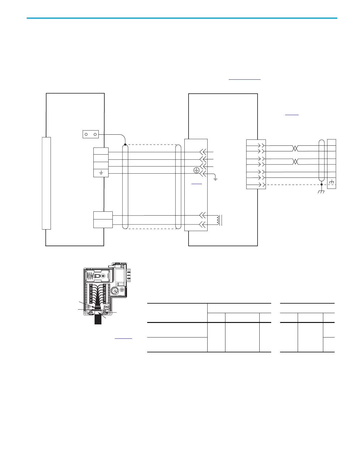
In this example, the Kinetix TLP servo-motor with rectangular connectors uses
a power/brake cable. Flying-lead feedback connections to the
2198-K53CK-D15M feedback connector kit are made by using bulk cable and
building your own cables. See Build Your Own Kinetix TLP Motor Cables
Installation Instructions, publication 2090-IN048
, for more information.
Figure 82 - Kinetix 5300 Drives with Kinetix TLP-A/B046…TLP-A/B100 Servo Motors
BR+
BR-
U
V
W
0
1
2
3
4
5
6
7
8
9
10
11
12
13
14
15
T+
T–
BAT+
BAT–
GND
+5VDC
2
5
8
1
4
7
5
10
6
14
GND
SHIELD
9
+
–
1
2
MBRK +
MBRK -
U
V
W
8
7
6
5
4
3
2
1
10
11
12
13
14
+
--
Motor Brake
Connector
Motor Power
Connector
2198-Cxxxx-ERS
Kinetix 5300 Drives
TLP-A046, TLP-A/B070,
TLP-A/B090, and TLP-A100
Servo Motors with
High-resolution Feedback
Motor Feedback
(MFB) Connector
Motor Power
Connector
Motor
Feedback
Connector
See connector kit
illustration (below)
for proper ground technique.
Use the 2198-K53CK-D15M
feedback connector kit when
building your own cables.
Ground Technique for
Feedback Cable Shield
360° exposed shield that
is secured under clamp.
Clamp Screws (2)
Clamp
See table on page 169 for note information.
2090-CTFB-MADD-CFAxx (standard) and
2090-CTFB-MADD-CFFxx (continuous-flex)
feedback cables do not require the
2198-K53CK-D15M feedback connector kit.
BROWN
BLUE
WHITE
WHT/RED
SHIELD
RED
WHITE
BLACK
GREEN/YELLOW
BROWN/RED
BLUE/BLACK
2090-CTPB-MADF-xxAxx
(standard) or
2090-CTPB-MADF-xxFxx
(continuous-flex)
Motor Power Cable
Tie Wrap
RED
BLACK
Cable Shield
Clamp
Note 5
Table 88 - Motor Power and Brake Cable Pinouts
Motor Power/Brake Cable
Cat. No.
Motor Power Motor Brake
Signal Wire Color Pin Signal Wire Color Pin
2090-CTPx-MADF-16
U
V
W
PE
RED
WHITE
BLACK
GREEN/YELLOW
1
2
4
5
BR+
BR–
BROWN
BLUE
3
6
2090-CTPx-MADF-18
5
6
See Table 88 for
motor power and
brake pinouts
2198-K53CK-D15M Feedback
Connector Kit
Refer to Kinetix 5300 Feedback Connector Kit
Installation Instructions, publication 2198-IN023
, for
connector kit specifications.

 Loading...


