Rockwell Automation Publication 2198-UM005C-EN-P - February 2022 37
Chapter 2 Plan the Kinetix 5300 Drive System Installation
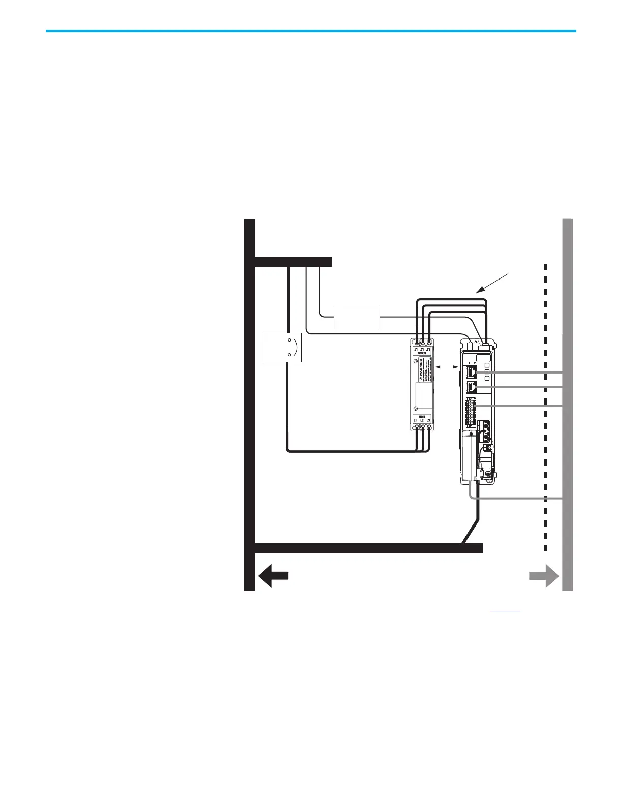
Establish Noise Zones
Observe these guidelines when routing cables used for Kinetix 5300 drives:
• The clean zone (C) is right of the drive system and includes the feedback
cables, digital inputs wiring, and Ethernet cable (gray wireway).
• The dirty zone (D) is above and below the drive system (black wireways)
and includes the circuit breakers, 24V DC power supply, safety, and
motor power cables.
• The very dirty zone (VD) is limited to where the AC line (EMC) filter VAC
output jumpers over to the drive (or the first drive when two or more
drives are zero-stacked together). Shielded cable is required only if the
very dirty cables enter a wireway. Keep filter wiring as short as possible.
Figure 14 - Noise Zones
(1) When space to the right of the drive does not permit 150 mm (6.0 in.) segregation, use a grounded steel shield instead. For
examples, refer to the System Design for Control of Electrical Noise Reference Manual, publication GMC-RM001.
C
D
D
VD
D
D
C
MBRK
W
V
U
1
10
1
2
MFB
50 mm
(1.97 in.)
Dirty Wireway
Clean Wireway
Motor Power Cables
Circuit
Protection
24V DC
Power Supply
AC Line Filter
(can be required for CE)
Kinetix 5300
Servo Drive
(1)
(1)
Very Dirty Filter/AC Input Connections
Segregated (not in wireway)
Route single motor cables
in shielded cable.
Route registration and communication
signals in shielded cables.
Hardwired Safety Cable
24V Input
Ethernet Cable
(shielded)
I/O Cable
Feedback Cable

 Loading...


