54 Rockwell Automation Publication 2198-UM005C-EN-P - February 2022
Chapter 4 Connector Data and Feature Descriptions
Digital Inputs and Auxiliary Feedback Connector Pinouts
The Kinetix 5300 drive has four configurable digital inputs and seven
configurable functions to choose from in the Logix Designer application.
Table 16 - Digital Inputs and Auxiliary Feedback Connector Pinouts
Although any input can be configured as a registration input, only two can be
registration inputs at any one time.
Table 17 - Configurable Functions
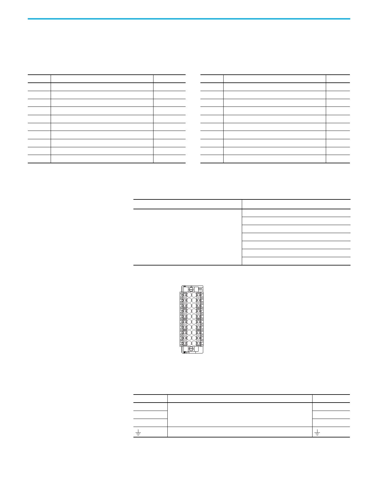
Figure 27 - Pin Orientation for Digital Inputs and Auxiliary Feedback Connector
Motor Power, Brake, and Feedback Connector Pinouts
Table 18 - Motor Power Connector
Pin Description Signal Pin Description Signal
1 24V current-sinking fast input #1. IN1 11 24V current-sinking fast input #3. IN3
2 I/O common for customer-supplied 24V supply. COM 12 I/O common for customer-supplied 24V supply. COM
3 24V current-sinking fast input #2. IN2 13 24V current-sinking fast input #4. IN4
4 I/O common for customer-supplied 24V supply. COM 14 I/O common for customer-supplied 24V supply. COM
5 I/O cable shield termination point. SHIELD 15 I/O cable shield termination point. SHIELD
6 AM Differential Input + AUX_AM+ 16 AM Differential Input – AUX_AM–
7 BM Differential Input + AUX_BM+ 17 BM Differential Input – AUX_BM–
8 IM Differential Input + AUX_IM+ 18 IM Differential Input – AUX_IM–
9 Encoder 5V power output AUX_EPWR_5V 19 Auxiliary common AUX_COM
10 Auxiliary feedback cable shield termination point. SHIELD 20 Auxiliary feedback cable shield termination point. SHIELD
Default Configuration
(1)
(1) Studio 5000 Logix Designer®, version 33 or later, is required to change from the default configuration.
Description
Digital input1= Enable
Digital input2 = Home
Digital input3 = Registration 1
Digital input4 = Registration 2
0 = Unassigned
1 = Enable
2 = Home
3 = Registration 1
4 = Registration 2
5 = Positive overtravel
6 = Negative overtravel
Pin Description Signal
U
Three-phase motor power
U
VV
WW
Chassis ground

 Loading...


