44 Rockwell Automation Publication 2198-UM005C-EN-P - February 2022
Chapter 3 Mount the Kinetix 5300 Drive System
Drill-hole Patterns Hole patterns for drives mounted in zero-stack or shared-bus configuration
are provided for mounting your drives to the panel.
• Frame 1 drives can be followed by only another frame 1 drive.
• Frame 2 drives can be followed by frame 1 drives or another frame 2
drive.
• Frame 3 drives can be followed by frame 1, frame 2, or another frame 3
drive.
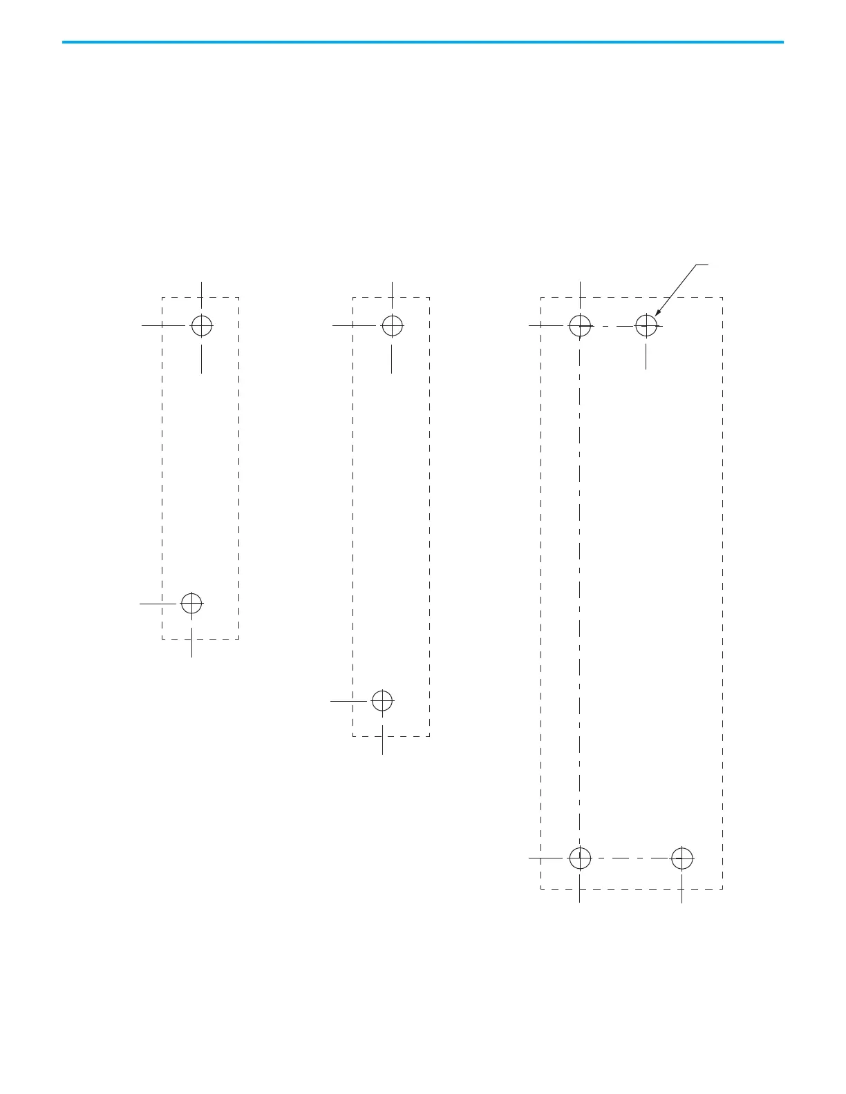
These hole patterns apply to standalone drives.
Figure 20 - Frame 1, Frame 2, and Frame 3 Standalone Hole Patterns
0
0
243.84
5.00
193.68
0
0
4.51
273.70
0
52.50
0
34.00
8x
ØM4 (#8-32)
Frame 3
Standalone Drive
Frame 1
Standalone Drive
Frame 2
Standalone Drive
Hole spacing is measured in millimeters and not
converted to inches to avoid errors due to rounding.

 Loading...


