92 Rockwell Automation Publication 2198-UM005C-EN-P - February 2022
Chapter 5 Connect the Kinetix 5300 Drive System
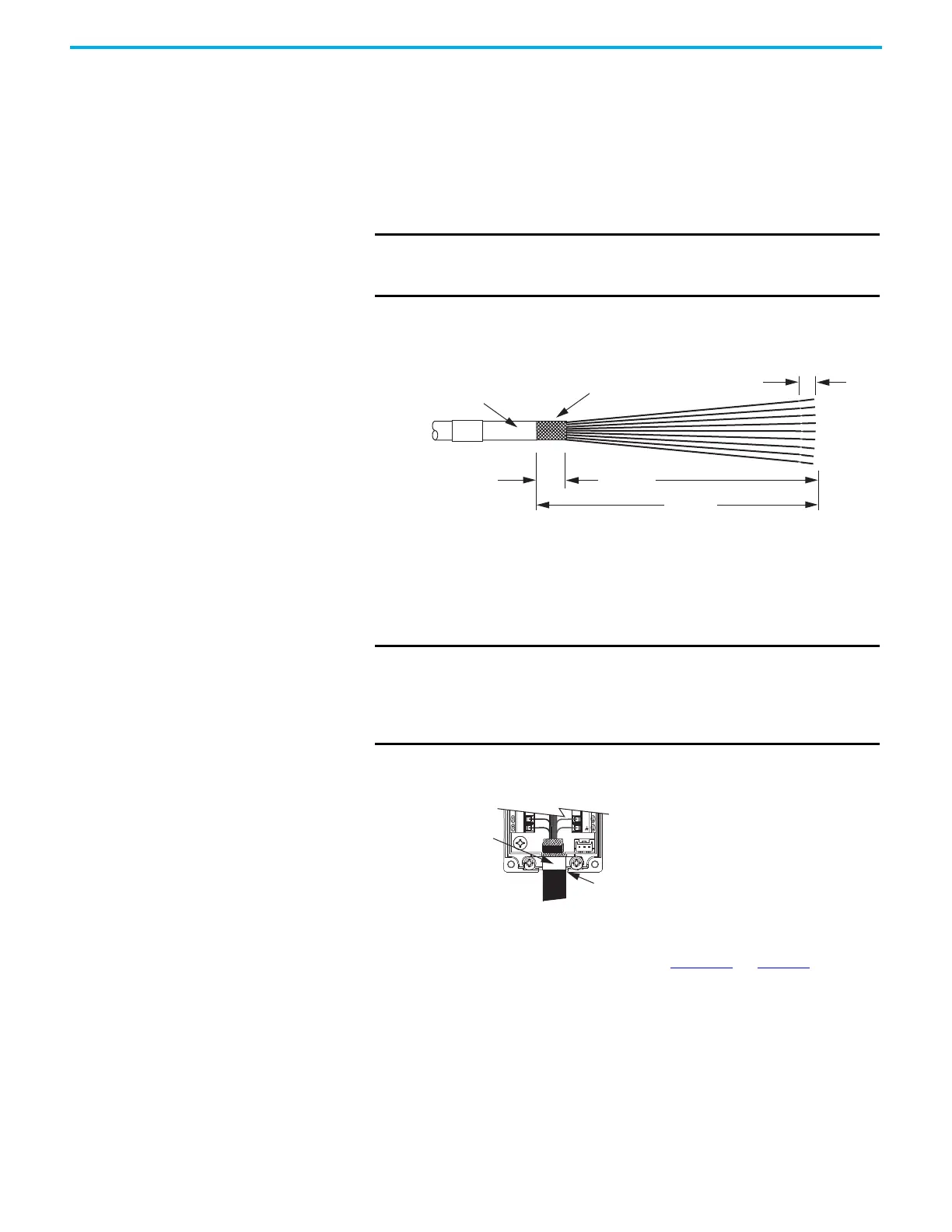
Motor Feedback Cable Preparation
When using the 2198-K53CK-D15M feedback connector kit, you must prepare
the Kinetix 2090 flying-lead conductors with the proper strip length. The cable
shield requires a high-frequency bond with the ground pad.
Follow these steps to prepare feedback cables.
1. Remove 110 mm (4.3 in.) of cable jacket and 97 mm (3.8 in.) of cable shield.
2. Determine the length for each wire and trim as necessary.
3. Remove 5 mm (0.2 in.) of insulation from the end of each wire.
Apply the Connector Kit Shield Clamp
Follow these steps to apply the connector kit shield clamp.
1. Position the 12 mm (0.5 in.) of exposed cable shield over the ground pad
to achieve a high-frequency bond.
2. Place the shield clamp over the cable shield and install the clamp screws.
Apply 0.34 N•m (3 lb•in) torque to each screw.
3. Route and insert each wire to its assigned terminal, apply 0.22 N•m
(1.9 lb•in) to 0.25 N•m (2.2 lb•in) maximum torque to each screw.
Refer to the connector pinout as shown in Figure 51
on page 95.
4. Attach the tie-wrap (customer-supplied) through the slots and around
the cable shield for stress relief and to create a high-frequency bond
between shield and ground pad.
IMPORTANT This length of wire is needed for the longest wires terminated at
each 8-pin connector. However, most wires are trimmed shorter,
depending on the terminal they are assigned to.
12.0 (0.5)
5.0 (0.2)
110 (4.3)
97 (3.8)
Cable Jacket
Cable Shield
Dimensions are in mm (in.)
IMPORTANT Cable preparation and positioning that provides a high-frequency
bond between the shield braid and clamp is required to optimize
system performance.
Also, make sure that the cable is positioned where the cover
clamps onto the jacket for added stress relief.
Shield Clamp
Cable positioned where the cover
clamps onto the cable jacket.

 Loading...


