50 Rockwell Automation Publication 2198-UM005C-EN-P - February 2022
Chapter 3 Mount the Kinetix 5300 Drive System
Mount Your Kinetix 5300
Drive
This procedure assumes you have prepared your panel and understand how to
bond your system. For installation instructions regarding other equipment
and accessories, refer to the instructions that came with those products.
Follow these steps to mount your Kinetix 5300 drives to the panel.
1. Lay out the hole pattern for each Kinetix 5300 drive in the enclosure.
For panel layout recommendations, refer to Establish Noise Zones
on
page 37.
2. Drill holes in the panel for mounting your drive system.
Hole patterns, by frame size, are shown in Drill-hole Patterns
beginning
on page 44.
3. Loosely attach the mounting hardware to the panel.
The recommended mounting hardware is M4 (#8-32) steel bolts. Observe
bonding techniques as described in HF Bond for Modules
on page 34.
4. Attach the leftmost drive to the cabinet panel.
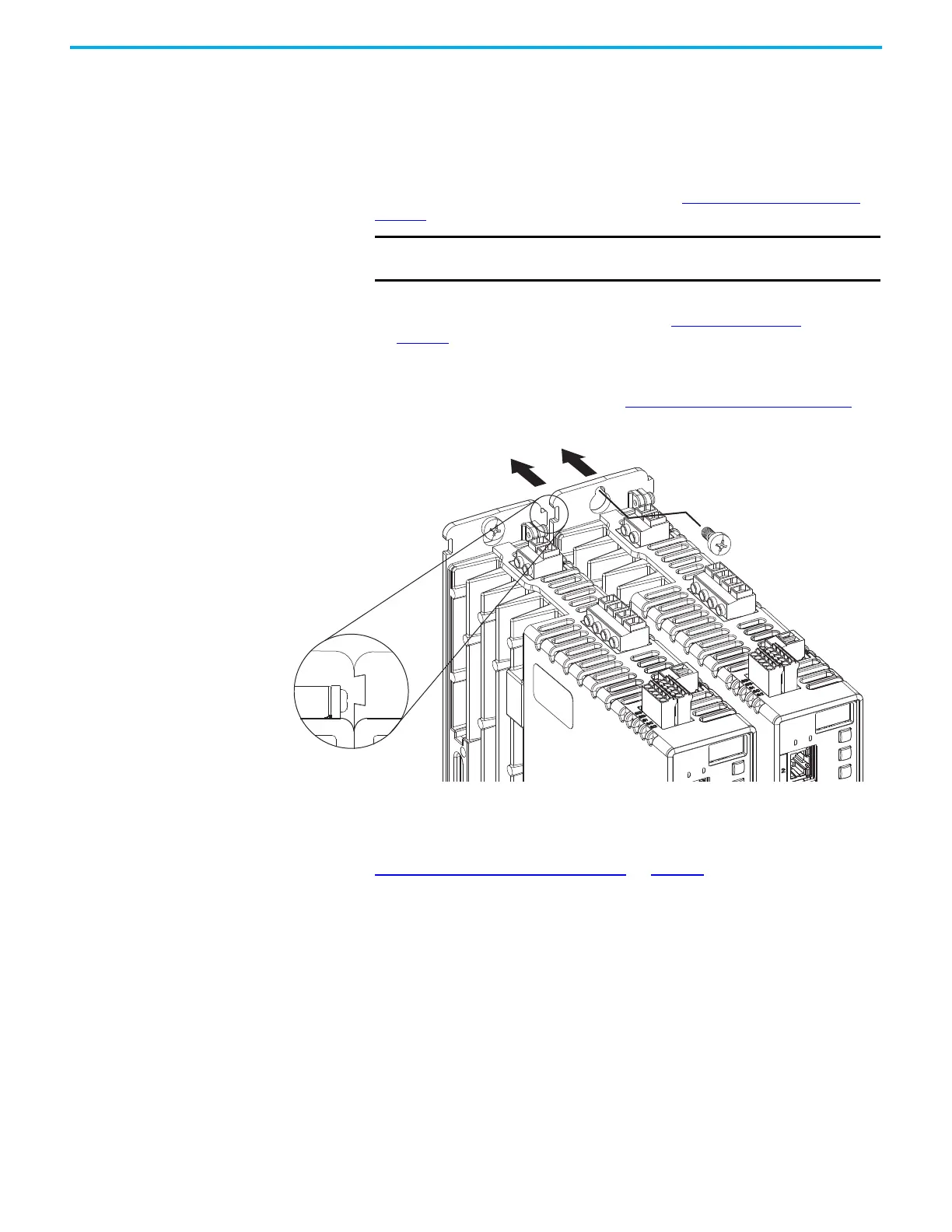
5. Attach additional drives (if any) just to the right of the previous drive by
using the same method, but also making sure the zero-stack tabs and
cutouts are engaged.
Zero-stack mounting is required based on configuration, refer to the
Zero-stack Tab and Cutout Example
on page 42.
6. Tighten all mounting fasteners.
Apply 2.0 N•m (17.7 lb•in) maximum torque to each fastener.
IMPORTANT To improve the bond between the Kinetix 5300 drive and subpanel,
construct your subpanel out of zinc plated (paint-free) steel.
Kinetix 5300 Servo Drives
(frame 1 drives shown)
Top Screws
(bottom screws not shown)
Zero-stack Tab
and Cutout Engaged

 Loading...


