System description
SIMOCODE pro
GWA 4NEB 631 6050-22 DS 03
1-113
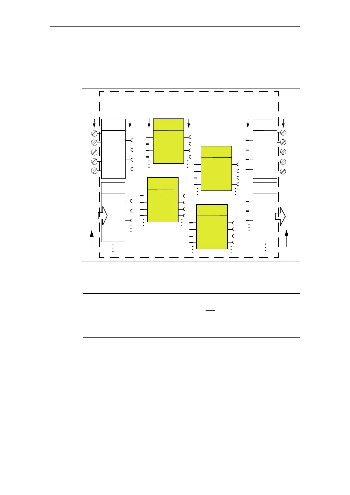
Schematic of principle structural configuration
The following function block diagram shows the principal configuration of
SIMOCODE pro with its external inputs and outputs and internally stored
function blocks:
Fig. 1-41: Principal configuration of SIMOCODE pro
Connecting plugs with sockets
Note
The function block plugs and sockets have not
already been connected at
the factory with the binary inputs and the relay outputs of the basic unit.
The internal wiring (connecting the plugs and sockets) is determined by the
selected application.
1)
Note
If external wiring has already been carried out, but SIMOCODE pro has not
yet been parameterized:
If you now press a button, the contactors will not be activated!
1)
1) If you select and load a preset application (e.g. the reversing starter) in
SIMOCODE ES, all links and interlocks for the reversing starter are created in
the basic unit.
1
2
3
1
2
Bit 0.0
Bit 0.1
Bit 0.2
Bit 0.0
Bit 0.1
Bit 0.2
IN1
IN2
IN3
IN4
4
OUT1
OUT2
OUT3
BU Inputs
Cyclic
Send
Cyclic
Receive
BU Outputs
3
DP
DP
From DP
Master
To DP
Master
PROFIBUS DP PROFIBUS DP
Function Block A
Function Block C
Function Block B
Inputs
(terminals)
Sockets Plugs Sockets
4
Outputs
(terminals)
Plugs
SIMOCODE pro (external) SIMOCODE pro (internal)
Standard function
Control Function
Logic Function
Standard function
Function Block D

 Loading...


