Logic modules
SIMOCODE pro
GWA 4NEB 631 6050-22 DS 03
11-23
11.11 Limit monitor
Description
Any analog values (2 bytes/1 word) can be monitored
for limit overshooting or limit undershooting. The limit monitor issues the
"Limit" signal at its socket. In addition, limit monitors can be "marked"
according to their function. Example: Monitoring the individual sensor
measuring circuits of the temperature module (Temperature 1 - 3) for
overtemperature.
The limit monitor consists of:
• One analog plug
• One logic component
• One socket.
Overall, there are 4 limit monitors (1 to 4) available for BU2.
Schematic
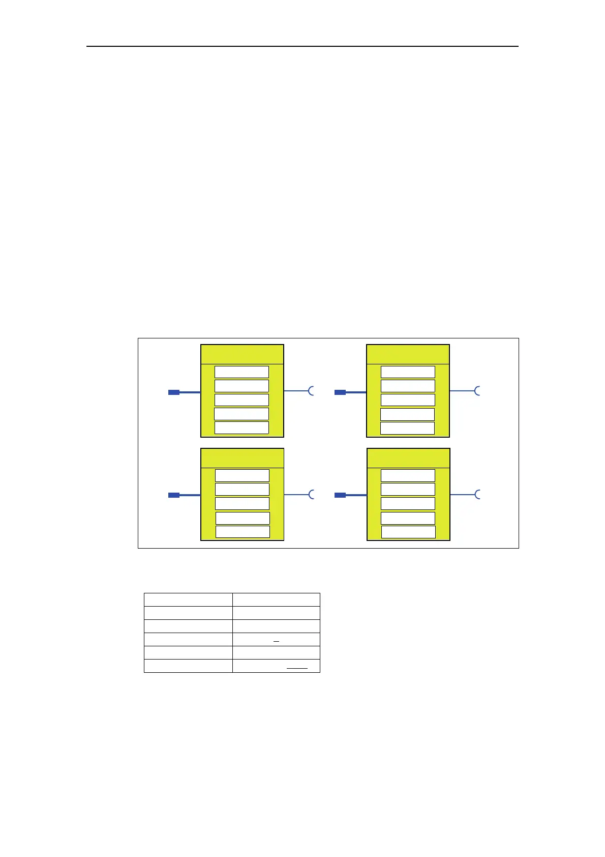
The following schematic shows the "Limit Monitor" logic modules:
Fig. 11-18: "Limit Monitor" logic modules
Response
Table 11-12: Limit response
See also "Tables of responses of SIMOCODE pro" in Chapter "Important
information".
Response Limit 1 to 4
Tripping -
Warning -
Signaling X
Disabled -
Delay 0 - 25.5 s (0.5 s)
Limit Monitor 1
Event -
Type
Limit
Activity
(Marking)
Limit value 1
Event -
Limit value 2
Limit Monitor 3
Event -
Type
Limit
Activity
Limit value 3
Limit Monitor 4
Event -
Type
Limit
Activity
Limit value 4
Response
(Marking)
Response
(Marking)
Response
Input Input
Input Input
Limit Monitor 2
Type
Limit
Activity
(Marking)
Response

 Loading...


