Logic modules
SIMOCODE pro
11-18 GWA 4NEB 631 6050-22 DS 03
11.8 Non-volatile elements
Description
Non-volatile elements behave like signal conditioners.
The output signals remain after failure of the supply voltage.
If an input signal is pending, the signal conditioner can issue an output
signal according to the chosen signal conditioner type:
• Non-inverting
• Inverting
• Edge rising with memory
• Edge falling with memory.
You can set the output response.
The non-volatile element consists of:
• Two plugs (input and reset)
• One logic component
• One socket.
Overall, the following are available:
–Two non-volatile elements 1 to 2 for BU1
– Four
non-volatile elements 1 to 4 for BU2.
Schematic
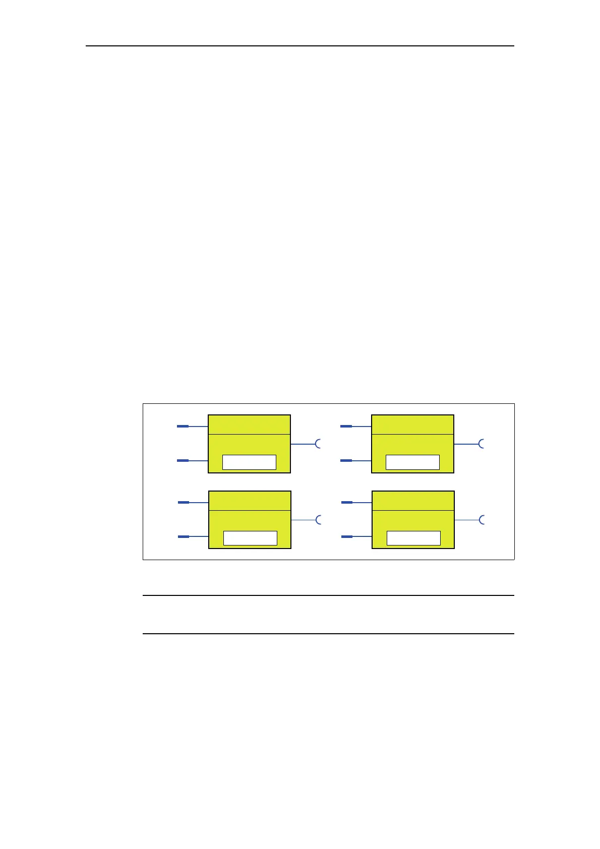
The following schematic shows the "Non-volatile Element" logic modules
Fig. 11-14: "Non-volatile Element" logic modules
Note
The output is always 0 if a reset is pending.
Non-vol. Elem. 1
Input
Reset
Output
Type
Non-vol. Elem. 2
Input
Reset
Output
Type
Non-vol. Elem. 1
Input
Reset
Output
Type
Non-vol. Elem. 2
Input
Reset
Output
Type

 Loading...


