Mounting, wiring, interfaces
SIMOCODE pro
GWA 4NEB 631 6050-22 DS 03
13-39
13.4.2 System interfaces on basic units, expansion modules, decoupling module,
current measuring modules and current/voltage measuring modules
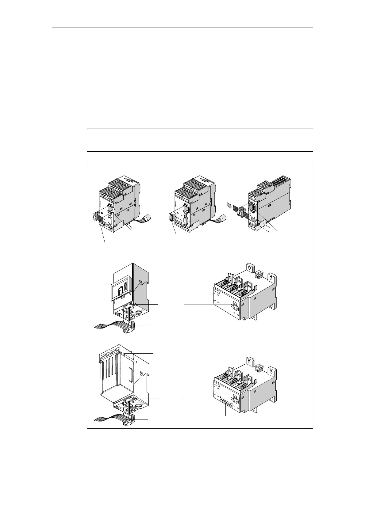
The system interfaces are located on the front and bottom of the basic
units. Other system components can be connected here:
• Via a connecting cable, e.g. digital modules, current measuring modules
• By plugging them in directly, e.g. addressing plugs and memory modules.
System interfaces not in use can be closed using the system interface
cover.
Notice
Only connect system interfaces when disconnected from voltage!
Fig. 13-27: Connecting system components to the system interface
Memory module,
Connecting cable
Expansion modules/Basic units
Current measuring modules
2 system
interfaces
System
interface
Connecting cable
System
interfaces
addressing plug,
System interface cover
Current/voltage measuring modules
System
interface
Connecting cable
Removable terminals
Removable terminals
Decoupling module

 Loading...


