Mounting, wiring, interfaces
SIMOCODE pro
13-42 GWA 4NEB 631 6050-22 DS 03
13.4.4 System interfaces on the operator panel and the operator panel with
display
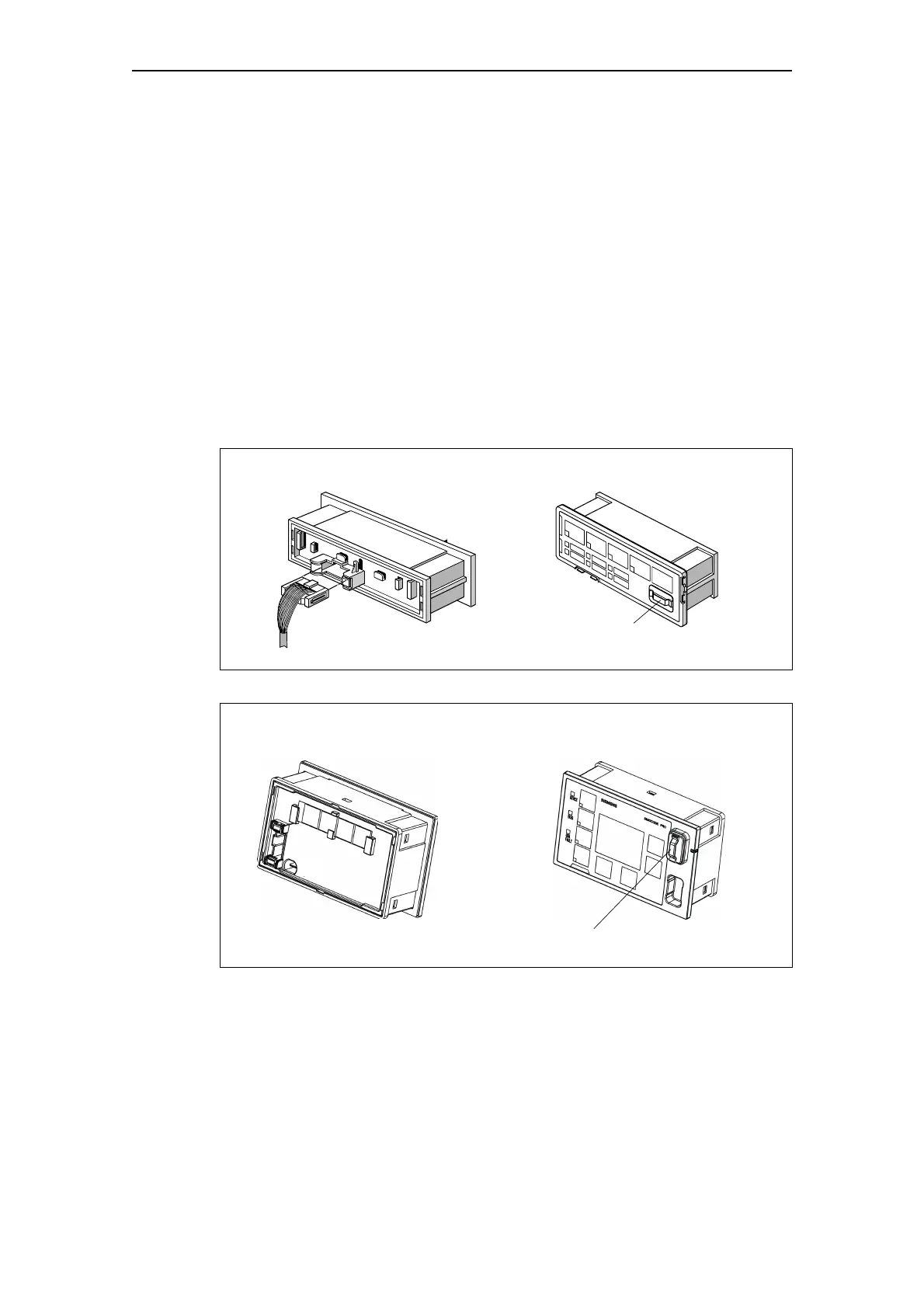
The operator panel has two system interfaces:
• Rear side system interface. This is not normally accessible on an integrated
operator panel. The incoming cable from the basic unit or expansion module
is always connected here.
• Front system interface. This is normally accessible on an integrated operator
panel. Components are only connected directly when needed, and removed
again after use.
These can be:
– Memory module
– Addressing plug
– PC cable for connecting a PC/programming device
– Cover (if the system interface is not in use).
Fig. 13-29: System interfaces on the operator panel
Fig. 13-30: System interfaces on the operator panel with display
Front system interface
e.g. memory module
Rear system interface
Connecting cable
Rear system interface Front system interface
e.g. memory module

 Loading...


