Commissioning and service
SIMOCODE pro
14-4 GWA 4NEB 631 6050-22 DS 03
14.2 Commissioning
14.2.1 Sequence
Please observe the information in the previous Chapter "General information
about commissioning and service" on Page 14-2.
To commission SIMOCODE pro, proceed as follows:
Table 14-1: Commissioning the basic unit
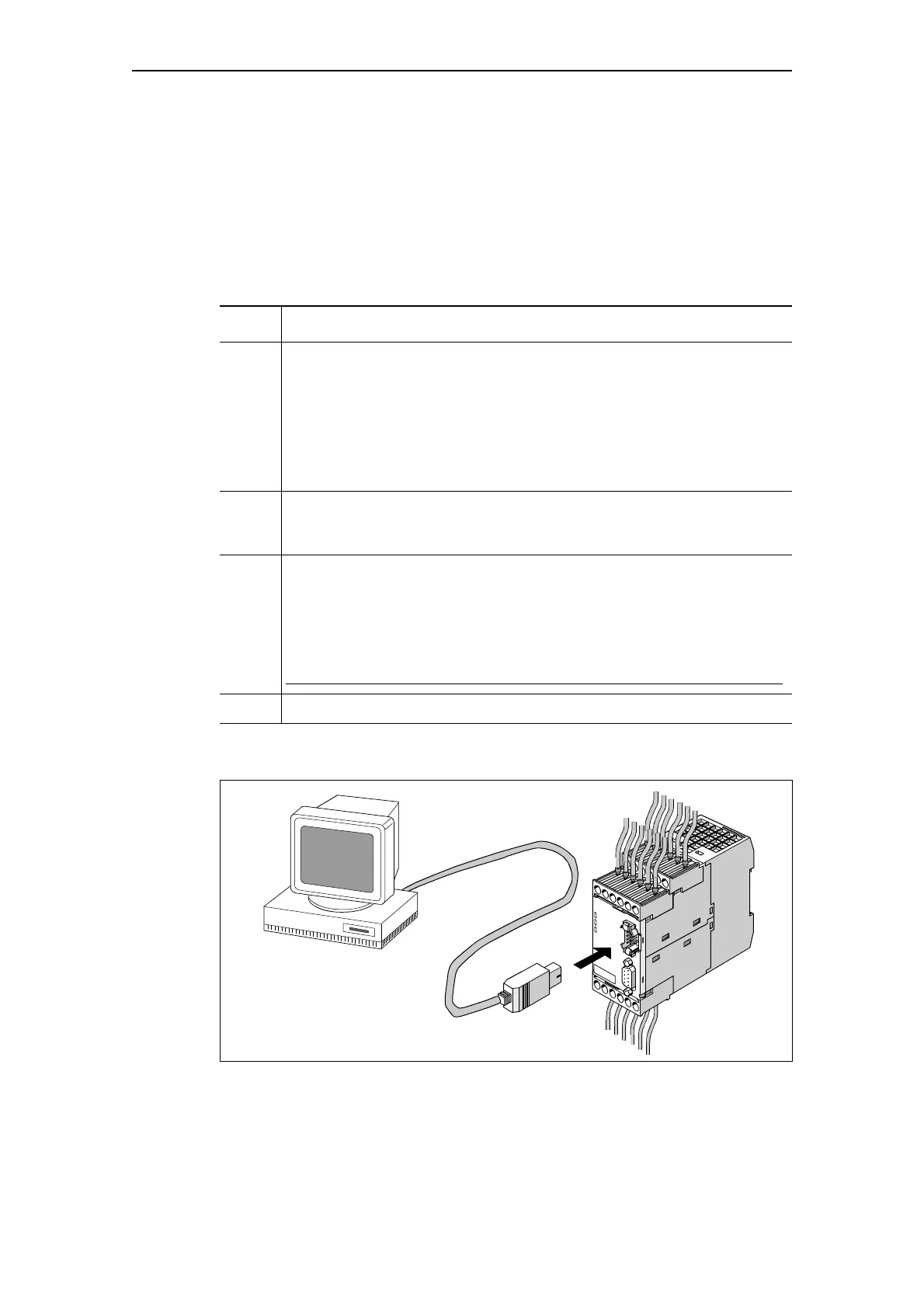
Fig. 14-1: Connecting a PC to the basic unit
Step Description
1 Switch on the supply voltage. In a fault-free state, the following LEDS should
light up or flash green:
• "Device" (lights up)
• "Bus" if PROFIBUS DP is connected (lights up or flashes).
Continue with step 2.
Otherwise, carry out diagnostics according to the LED display.
You will find further information in Chapter 14.2.3 "Diagnostics via LED display
on the basic unit and on the operator panel". Try to rectify the fault.
2 If you wish to make SIMOCODE pro available on the PROFIBUS DP, set the
PROFIBUS DP address. You will find further information about this in Chapter
"Setting the PROFIBUS DP address" on Page 14-5.
3 Parameterize SIMOCODE pro or check the existing parameterization e.g. with
a PC via SIMOCODE ES software.
For this, connect the PC/programming device to the system interface with the
PC cable (see the figure below).
Notice
For basic unit 1 (SIMOCODE pro C), only use the front system interface!
4 Start SIMOCODE ES.
PC cable,
Order No. 3UF7940-0AA00-0

 Loading...


