Logic modules
SIMOCODE pro
11-8 GWA 4NEB 631 6050-22 DS 03
11.5 Counter
Description
Counters are integrated in the SIMOCODE pro system. These are activated
via the plugs "+" or "-".
The counter output switches to "1" when the preset limit is reached. The
counter is reset with "Reset".
The actual value is available as a socket for further processing and can also
be transmitted to the automation system.
• Plug +: Increases the actual value by 1 (maximum: limit)
• Plug –: Decreases the actual value by 1 (minimum: 0).
• Reset: Resets the actual value to 0.
The counter consists of:
• 3 plugs (input +, input – and reset)
• One logic component
• One socket.
• One "Actual value" analog socket with the current value in the range between
0 and the limit. It remains even if there is a voltage failure.
Overall, the following are available:
– Two counters, 1 to 2 for BU1
– Four counters, 1 to 4 for BU2.
Schematic
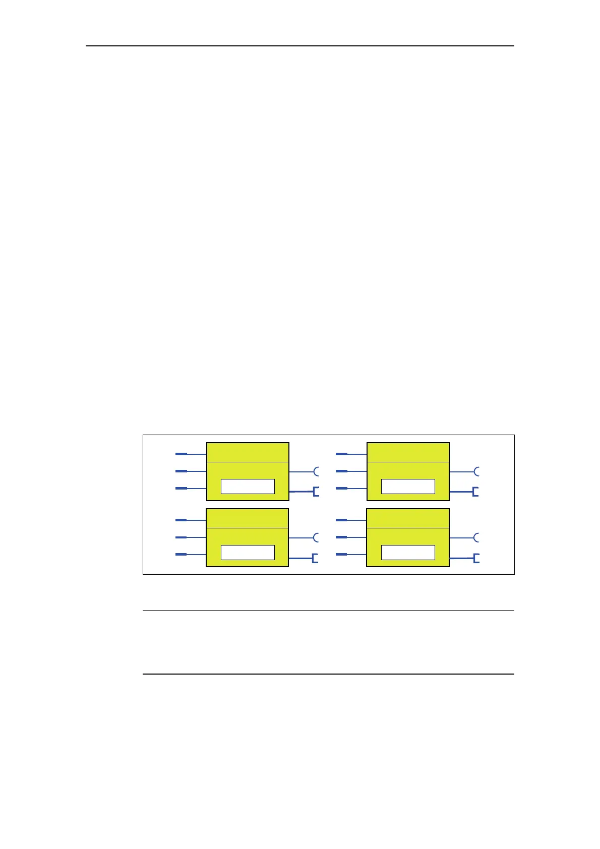
The following schematic shows the "Counter" logic modules:
Fig. 11-8: "Counter" logic modules
Note
The time between the events to be counted depends on:
- The input delay
- The device cycle time.
Counter 1
Input +
Input –
Reset
Output
Counter 2
Input +
Input –
Reset
Output
Limit Limit
Counter 3
Input +
Input –
Reset
Output
Counter 4
Input +
Input –
Reset
Output
Limit Limit
Actual value Actual value
Actual value Actual value

 Loading...


