Data formats and data records
SIMOCODE pro
GWA 4NEB 631 6050-22 DS 03
B-21
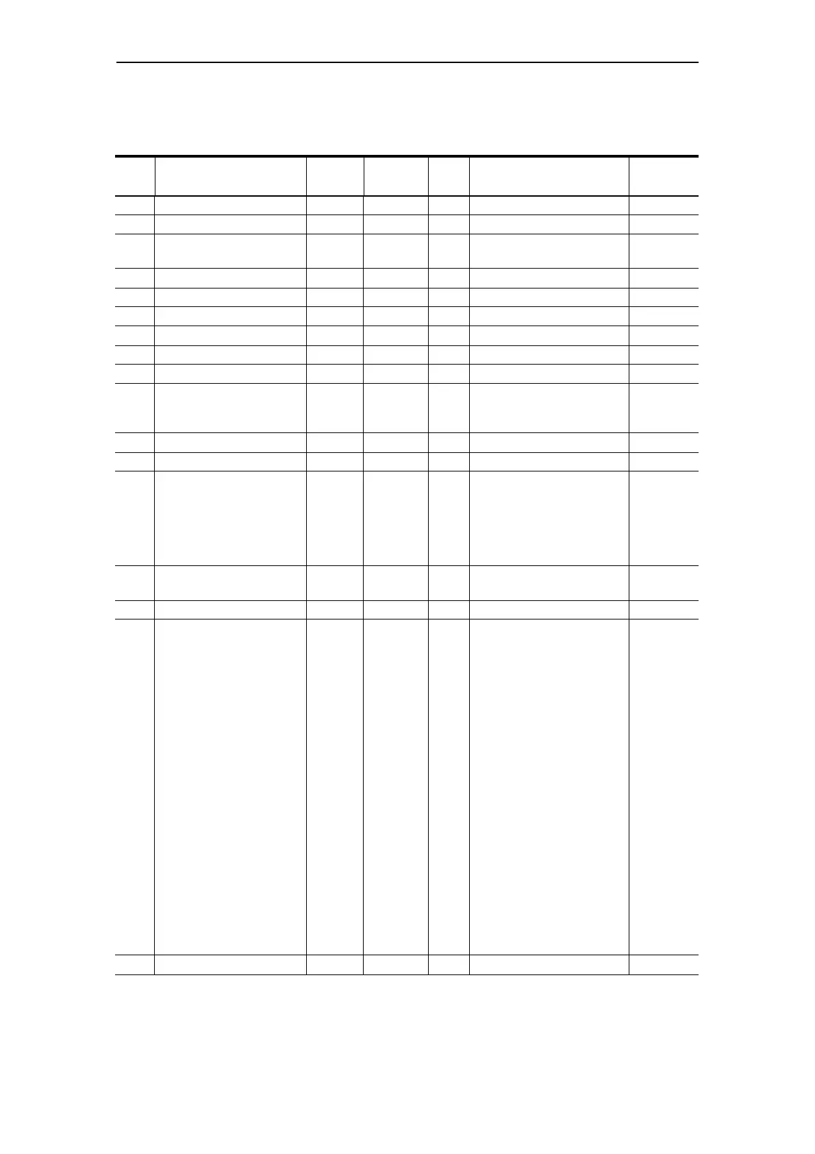
B.11 Data record 130 - Basic device parameters 1
Byte
Bit
Designation
(PRM group)
Type Range De-
fault
Note Informa-
tion
0.0 Reserved Byte[4]
4.0 Device configuration (12) Byte[8] BU1 BU2
4.0 Device class Byte 5, 9 5 = BU1
9=BU2
BU1 BU2
BU2
5.0 Thermistor (Th) Bit 0, 1 1 = active; thermistor in the BU BU1 BU2
5.1 Reserved Bit[7]
6.0 Operator panel (OP or OPD) Bit 0, 1 BU1 BU2
6.1 Analog module (AM) Bit 0, 1 BU2
6.2 Temperature module (TM) Bit 0, 1 BU2
6.3 Earth-fault module (EM) Bit 0, 1 BU2
6.4 Digital module 1 (DM1) Bit[2] 0 .. 2 0 = no digital module
1 = monostable
2=bistable
BU2
6.6 Digital module 2 (DM2) Bit[2] 0 .. 2 BU2
7.0 Reserved Bit[8]
8.0 Current measuring module
(IM/UM)
Bit[7] 0 .. 5 0 = no current measurement
1=0.3 A-3 A
2=2.4 A-25 A
3 = 10 A - 100 A
4 = 20 A - 200 A
5 = 63 A - 630 A
BU1 BU2
8.7 Voltage measuring module
(UM)
Bit 0, 1 BU2
9.0 Reserved
10.0 Control function (CF) 0x00
0x10
0x11
0x12
0x20
0x21
0x30
0x31
0x40
0x41
0x50
0x60
0x61
0x62
0x63
0x64
0x70
0x71
0x00 = Overload
0x10 = Direct starter
0x11 = Reversing starter
0x12 = Linked device
0x20 = Star-delta starter
0x21 = Star-delta
reversing starter
0x30 = Dahlander
0x31 = Dahlander
reversing starter
0x40 = Pole-changing starter
0x41 = Pole-changing
reversing starter
0x50 = Solenoid valve
0x60 = Positioner 1
0x61 = Positioner 2
0x62 = Positioner 3
0x63 = Positioner 4
0x64 = Positioner 5
0x70 = Soft starter
0x71 = Soft starter with
reversing contactor
BU1 BU2
BU1 BU2
BU1 BU2
BU1 BU2
BU2
BU2
BU2
BU2
BU2
BU2
BU2
BU2
BU2
BU2
BU2
BU2
BU2
BU2
11.0 Reserved Bit[8]
Table B-12: Data record 130 - Basic device parameters 1

 Loading...


