Logic modules
SIMOCODE pro
11-2 GWA 4NEB 631 6050-22 DS 03
11.1 Introduction
Description
Freely programmable logic modules are function blocks that process input
signals and provide binary or analog output signals according to their
internal logic components. Logic modules can contain:
• Plugs
• An internal logic component
•Sockets
• Settings, e.g. the time for a timer.
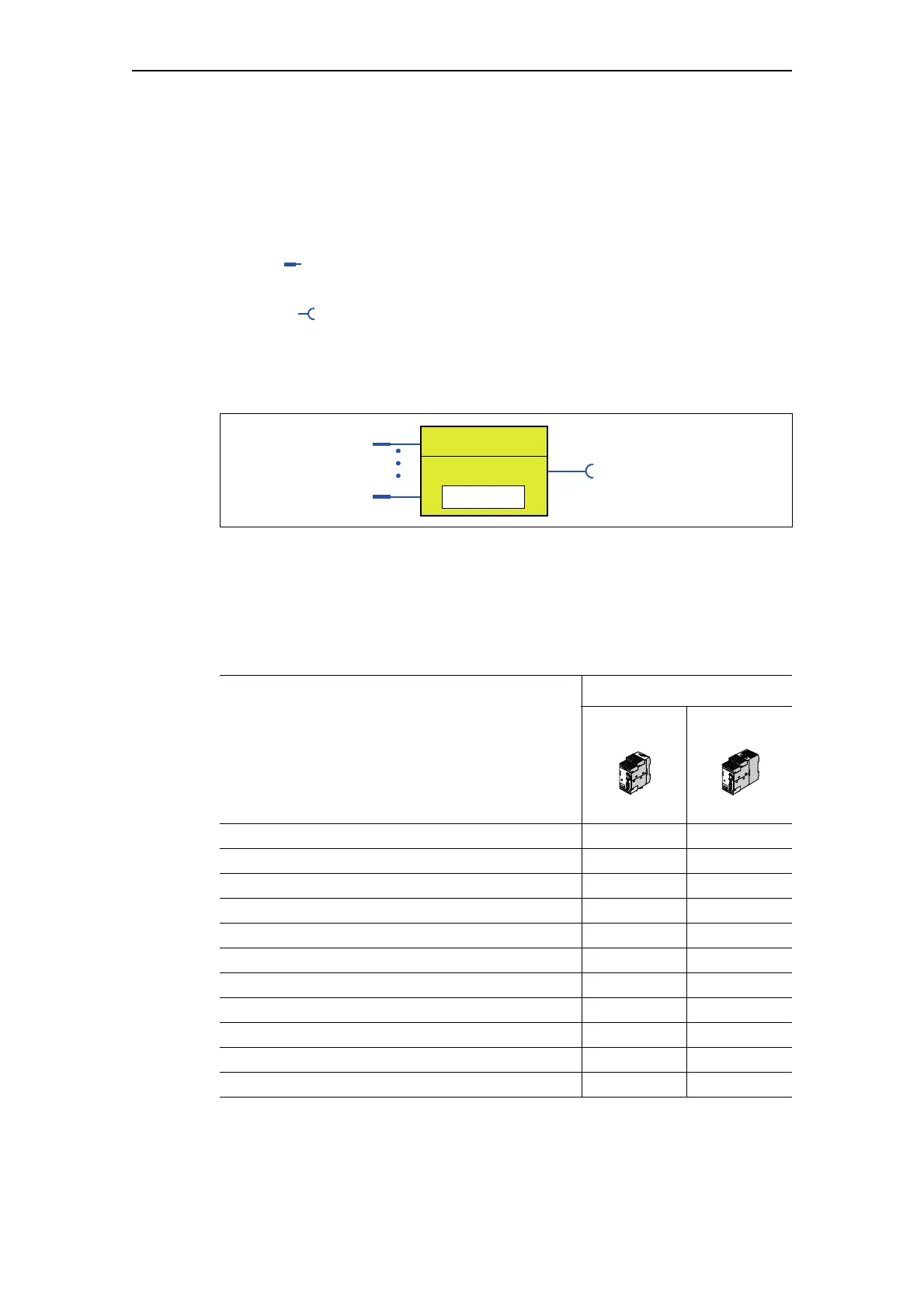
Schematic
The following schematic shows a general representation of a logic module:
Fig. 11-1: General representation of a logic module
Extent and application
You can use the logic modules to carry out additional functions for your
application. These can be used, for example, to implement logical
operations, time relay functions and counter functions. Depending on the
device series, the system provides several logic modules:
SIMOCODE
Logic module pro C
BU1
Number
pro V
BU2
Number
Truth tables 3 inputs/1 output 3 6
Truth tables 2 inputs/1 output — 2
Truth tables 5 inputs/2 outputs — 1
Timer 2 4
Counter 2 4
Signal conditioners 2 4
Non-volatile elements 2 4
Flashing 3 3
Flickering 3 3
Limit Monitor — 4
Calculation modules (Calculator)* — 2
Table 11-1: Freely-programmable logic modules
*) Only for basic unit 2 for version *E03* onwards
Logic module
Plug 1
Plug n
Socket 1 - n
(Logic component)
Setting value

 Loading...


