Commissioning and service
SIMOCODE pro
14-6 GWA 4NEB 631 6050-22 DS 03
14.2.3 Diagnostics via LED display on the basic unit and on the operator panel
The basic units and the operating panel have three LEDs for displaying
specific device states:
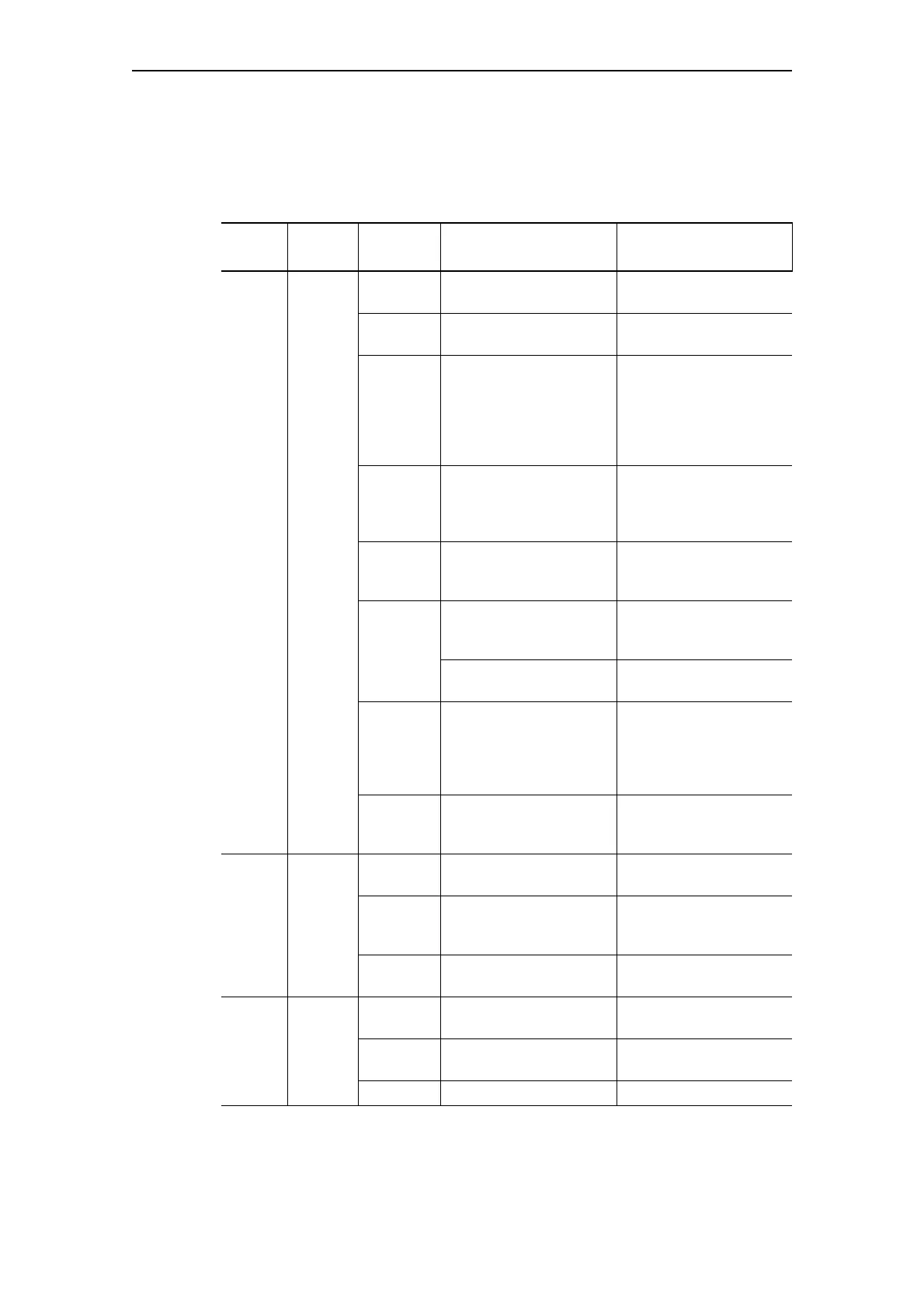
Table 14-4: Diagnostics via LED display
LED Status Display Description Corrective measures for
faults
Device Device
status
Green Device is ready for
operation
—
Green –
flickering
Internal fault Send back the basic unit
Yellow Memory module or
addressing plug
recognized, Test/Reset
buttons control the
memory module or
addressing plug
—
Yellow –
flashing
Memory module/
addressing plug read in;
factory settings
configured (duration: 3s)
—
Yellow –
flickering
Memory module
programmed (duration:
3s)
—
Red Parameterization
incorrect (also Gen.
Fault on)
Parameterize again and
switch the control
voltage off and on again
Basic unit defective
(also Gen. Fault on)
Replace basic unit!
Red –
flashing
Memory module,
addressing plug,
expansion modules
defective (also Gen.
Fault on - flashing)
Reprogram/replace the
memory module,
replace the expansion
modules
Off Supply voltage too low Check whether the
supply voltage is
connected/switched on
Bus Bus
status
Off Bus not connected or
bus fault
Connect the bus or
check bus parameters
Green –
flashing
Baud rate recognized/
communication with
PC/programming device
—
Green Communication with
PLC/PCS
—
Gen.
Fault
Fault
status
Red Fault pending; reset has
been saved
Rectify fault, e.g.
overload
Red –
flashing
Fault pending; reset has
not been saved
Rectify fault, e.g.
overload
Off No fault —

 Loading...


