Mounting, wiring, interfaces
SIMOCODE pro
13-14 GWA 4NEB 631 6050-22 DS 03
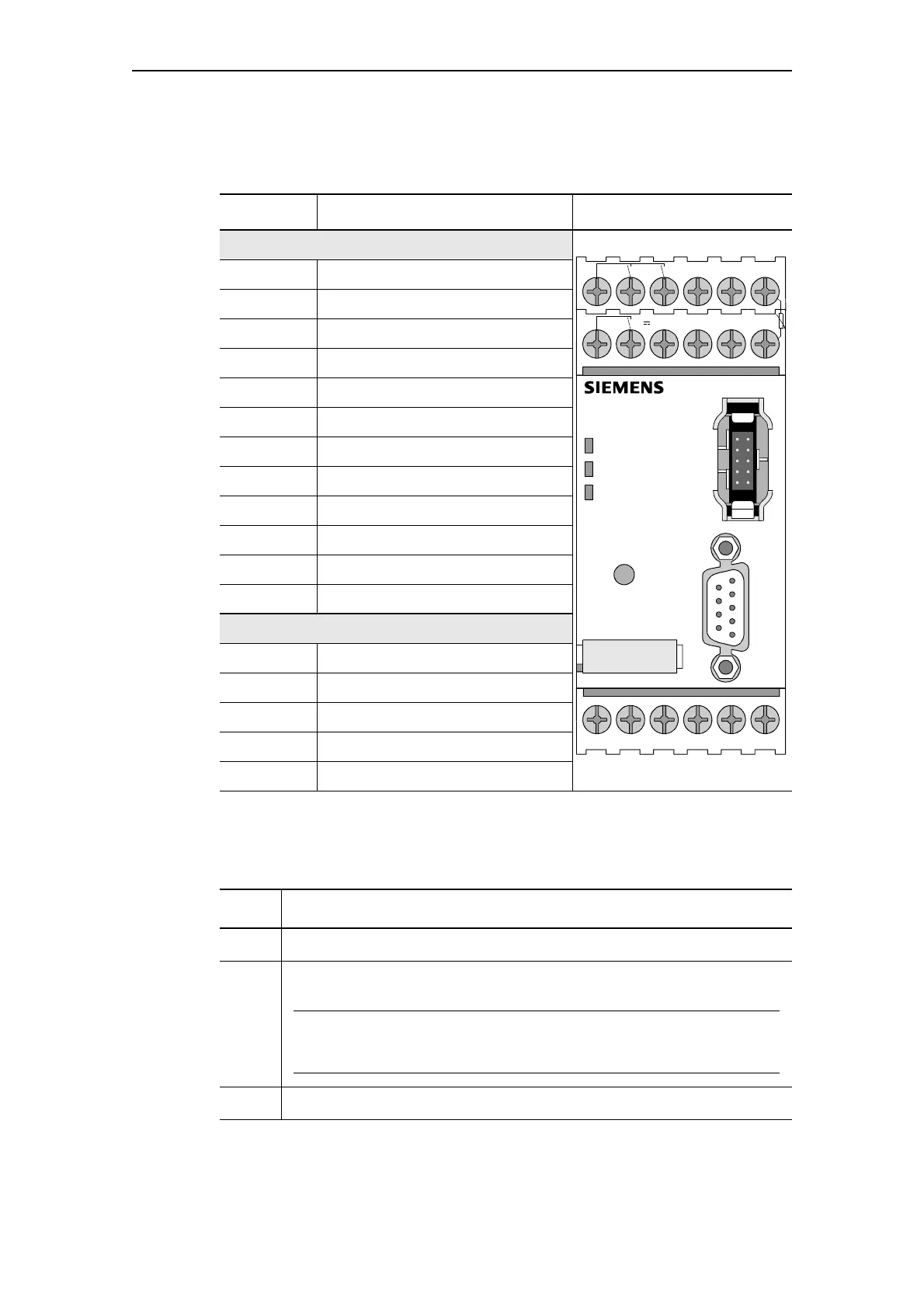
Basic unit pin assignment
The following table shows the pin assignment of the removable terminals:
Table 13-4: Pin assignment for the removable terminals of the basic unit
Sequence for wiring the removable terminals for basic units
Proceed as follows:
Table 13-5: Wiring the removable terminals of the basic unit
Connection Assignment
Upper terminals
1 Ground for relay outputs 1 and 2
2 Relay output OUT1
3 Relay output OUT2
4 Digital input IN3
5 Digital input IN4
T2 Thermistor connection (binary PTC)
6 Relay output OUT3
7 Relay output OUT3
8 24 V DC only for IN1 to IN4
9 Digital input IN1
10 Digital input IN2
T1 Thermistor connection (binary PTC)
Lower terminals
A1 Pin 1 supply voltage
A2 Pin 2 supply voltage
A PROFIBUS DP pin A
B PROFIBUS DP pin B
SPE/PE System shielding
Step Description
1 Connect the cables to the upper and lower terminals.
2 If you wish to use the A/B terminals for PROFIBUS DP, connect the
PROFIBUS DP cable-shielding to the SPE/PE terminal.
Notice
The A/B terminals are an alternative to the 9-pole SUB-D connection! Baud
rates of up to 1.5 MBit/s are possible!
3 Connect the system shielding to the SPE/PE terminal.
1 OUT1 2 .2 3 4 IN3 IN4 5T2
OUT3 789IN1 IN2 10 T16
DEVICE
BUS
GEN. FAULT
ϑ
TEST/
RESET
PROFIBUS DP
A1 A2 A B SPE/PE
24V
SIMOCODE PRO

 Loading...


