Short instructions for configuring a reversing starter
SIMOCODE pro
GWA 4NEB 631 6050-22 DS 03
2-7
General procedure for parameterizing a reversing starter
Parameterization means:
1. Setting values
2. Connecting function blocks
Where this example is concerned, this means:
• Select the control function "Reversing Starter". This establishes all the
interlocks and connections for the reversing starter in the basic unit.
• Determine the set current I
s
for motor protection. In this case, the set current
corresponds to the motor rated current, i.e. 3 A.
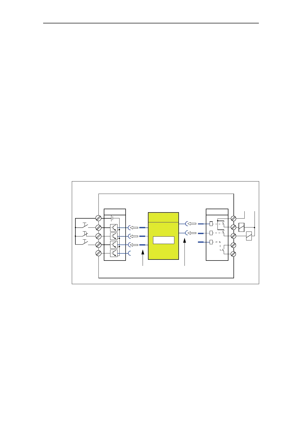
• The "BU Outputs" function block must be connected to the sockets of the
"Protection/Control" function block via the software, i.e:
– "BU Output 1" plug to "Contactor Control QE1" socket (right)
– "BU Output 2" plug to "Contactor Control QE2" socket (left).
• The plugs on the "Protection/Control" function block must be connected via
software to the sockets on the "BU Inputs" function block, i.e.
– Control station plug - Local Control [LC] ON< to "BU Input 1" socket
– Control station plug - Local Control [LC] OFF to "BU Input 2" socket
– Control station plug - Local Control [LC] ON> to "BU Input 3" socket.
Fig. 2-3: Schematic of a parameterization example
The assignment of the contactor controls QE depends on the parameterized
control function. See Chapter 4.3 "Active control stations, contactor
controls, lamp controls and status information for the control functions".
SIMOCODE pro
• Connect
relay outputs
1
2
1
2
3
BU Inputs
Control station - Local Control [LC] Contactor controls
• Select reversing starter
• Set I
s
• Connect
digital inputs
BU Outputs
QE1
QE2
ON<
OFF
ON>
Protection/Control
I
s
= 3 A
Right
Left

 Loading...


