Mounting, wiring, interfaces
SIMOCODE pro
13-32 GWA 4NEB 631 6050-22 DS 03
Safety guidelines
Note
Measuring voltage or power values:
For current/voltage measuring modules, connect the main circuit L1, L2, L3
with the connection terminals (L1, L2, L3) of the removable terminals via a
3-core cable. The supply cables may require additional cable protection, for
example, via short-circuit proof cable or fuses.
Notice
When connecting or routing the cables of the individual phases of the main
circuit, ensure correct assignment of the phases on the current/voltage
measuring modules and correct routing direction! Observe the information
in the operating instructions!
You can find the operating instructions for SIMOCODE pro at:
www.siemens.com/industrial-controls/manuals.
Removable terminals
The following table shows cable cross sections, strip lengths and tightening
torques of the cables for the removable terminals:
Table 13-15: Cable cross sections, strip lengths and tightening torques of the cables
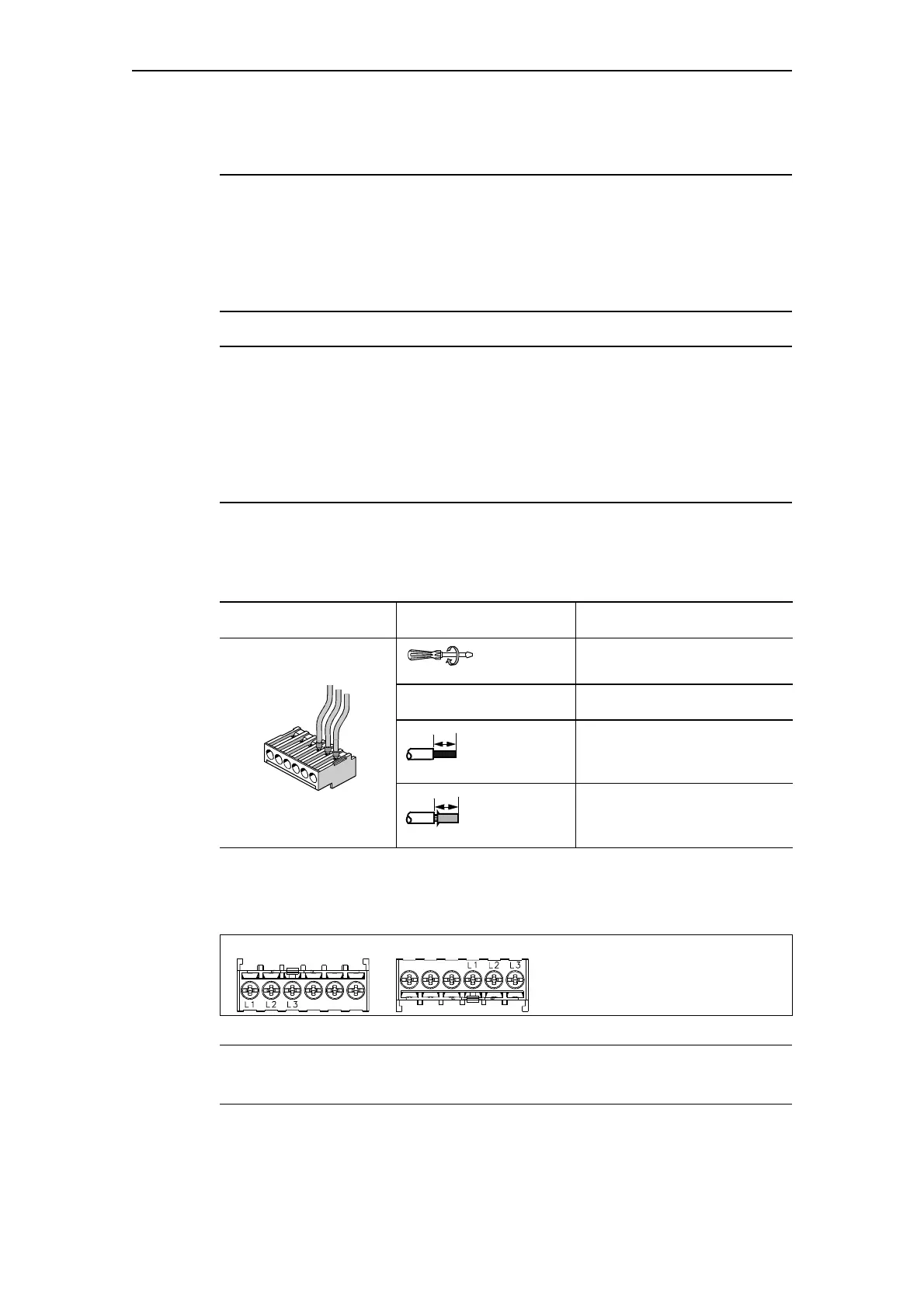
The following is a representation of the pin assignment of the removable
terminals:
Fig. 13-19: Pin assignment of the terminals of the current/voltage measuring modules
Caution
The L1 and L3 phases are interchanged on the upper/lower terminals!
Removable terminals Screwdriver Tightening torque
TORQUE: 7 LB.IN - 10.3 LB.IN
0.8 Nm - 1.2 Nm
Strip lengths Cable cross section
2 x 0.5 mm
2
- 2.5 mm
2
/
1 x 0.5 mm
2
- 4 mm
2
2 x AWG 20 to 14/1x AWG 20 to 12
2 x 0.5 mm
2
- 1.5 mm
2
/
1 x 0.5 mm
2
- 2.5 mm
2
2x AWG 20 to 16/1x AWG 20 to 14
10
Finely stranded
with/without
end sleeve
L1, L2, L3:
Terminals for connecting the 3-wire
cable of the main circuit
Bottom
Upper

 Loading...


