TB8100 Service Manual Power Amplifier Circuit Description 117
© Tait Electronics Limited September 2006
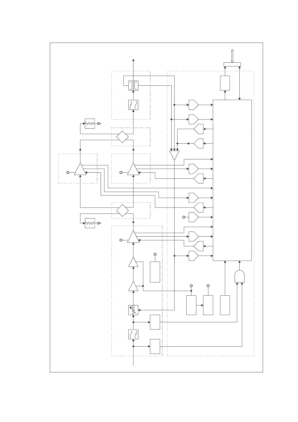
Figure 7.2 PA control, RF and power supply circuitry block diagram
60W
High Pass
Filter
Directional
Coupler
Low Pass
Filter
PIN
Attenuator
100mW
Gain Block
Final
6W Board
Control Board
LPF/Directional Coupler Board
Microprocessor
60W
Board
60W
Board
Combiner
Board
Splitter
Board
Driver
6W
50
Load
Ω 50
Load
Ω
1W
Pre-driver
RF In RF Out
RF
Block
RF
Detect
DACDACDACDACDAC
ADCADC ADC ADC ADC ADC ADC
AND
power control
driver current
driver temperature
final 2 drive current
final 1 drive current
driver bias
final 2 bias
final 2 temperature
final 1 temperature
final 1 bias
RF power setting
transient wave shape
forward power
reverse power
ambient air temperature
+10V Power
Supply
+5V Power
Supply
Fan
Buffer
-3V Power
Supply
+2.5V Power
Supply
+10V
-3V
PA_KEY
I C
2
System
Control
Bus
+28V
+28V
60W
Final
+28V
This drawing shows the
circuitry for the 100W PA.

 Loading...


