TB8100 Service Manual Power Amplifier Board Replacement 181
© Tait Electronics Limited September 2006
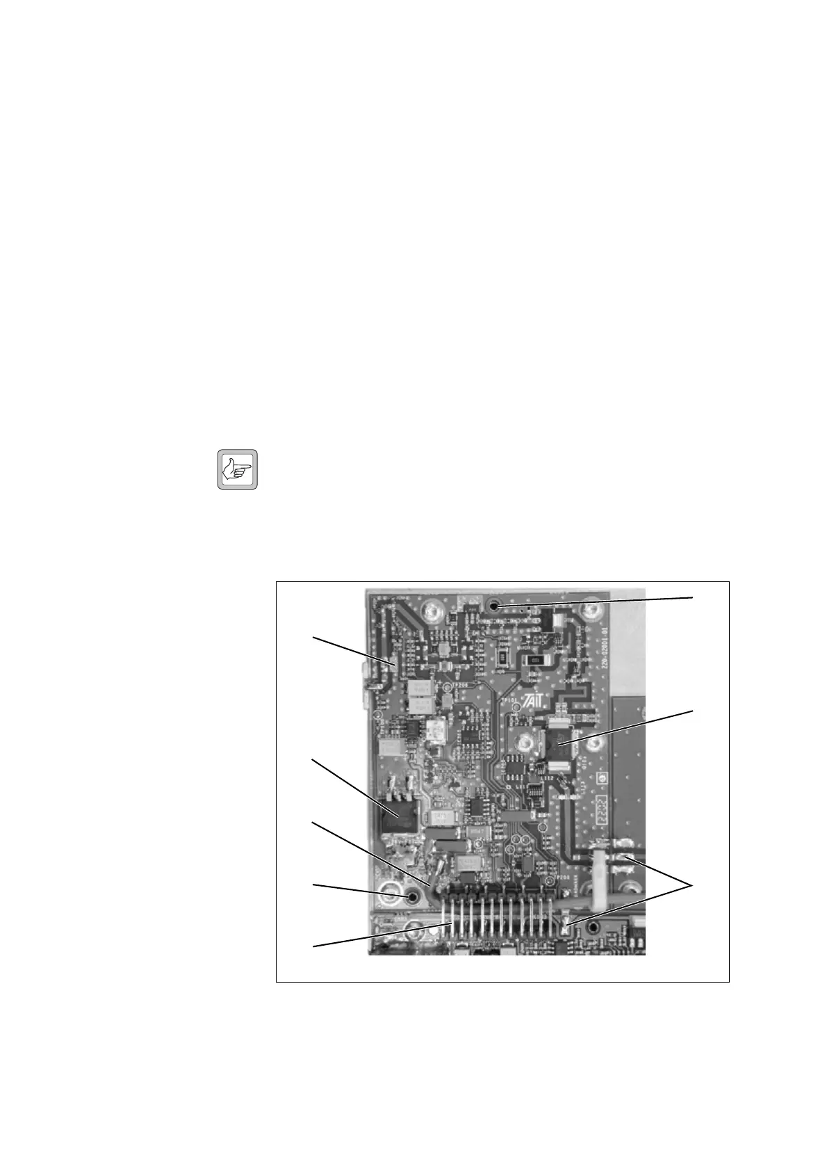
3. If necessary, desolder the +28VDC power feed wire c.
4. Desolder the RF links
d connecting the board to any adjacent
boards.
5. Remove the M3 Torx screws securing the board to the heatsink.
6. Carefully lift the board directly upwards off the locating pins
e and
remove it from the heatsink.
Refitting 1. Ensure the heatsink and bottom of the board are clean. Remove any
old heatsink compound.
2. Apply a thin layer of fresh heatsink compound to the bottom of the
board underneath Q103
f, D200 g and AT100 h (if fitted). Use
as little as possible, while still covering the whole of the mounting area
of each component.
3. Refit the board, following the removal instructions in reverse order.
Note Before tightening the screws, press the board down over the locat-
ing pins so that it is firmly seated against the heatsink. Then
tighten the M3 Torx screws to the correct torque.
4. Refit the front panel and cover.
Figure 10.2 Replacing the 6W board
b
c
d
f
g
h
e
e

 Loading...


