TB8100 Service Manual Reciter Circuit Description 61
© Tait Electronics Limited September 2006
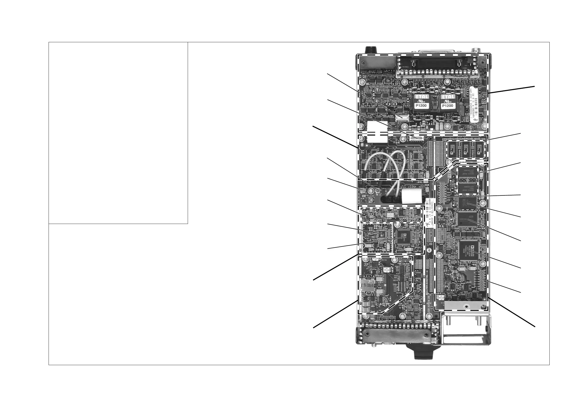
Figure 2.14 Identifying the circuitry on the digital and system interface boards
b
system interface board
c
CODECs
d
SRAM
e
RISC JTAG connector (factory use only)
f
flash memory
g
RISC
h
DSP
i
DSP JTAG connector (factory use only)
j
main digital system
1)
power supply
1!
digital IF and clock
1@
DDC
1#
ADC
1$
40MHz digital clock
1%
16.9MHz IF (VHF) / 70.1MHz IF (UHF)
1^
12.8MHz reference
1&
audio
1*
high speed data connector
1(
third-party connector
VHF (B-band) reciter shown fitted
with isolated system interface board
b
c
d
f
g
h
j
1)
1!
1@
1#
1$
1%
1^
1&
1*
e
i
1(

 Loading...


