42 Reciter Circuit Description TB8100 Service Manual
© Tait Electronics Limited September 2006
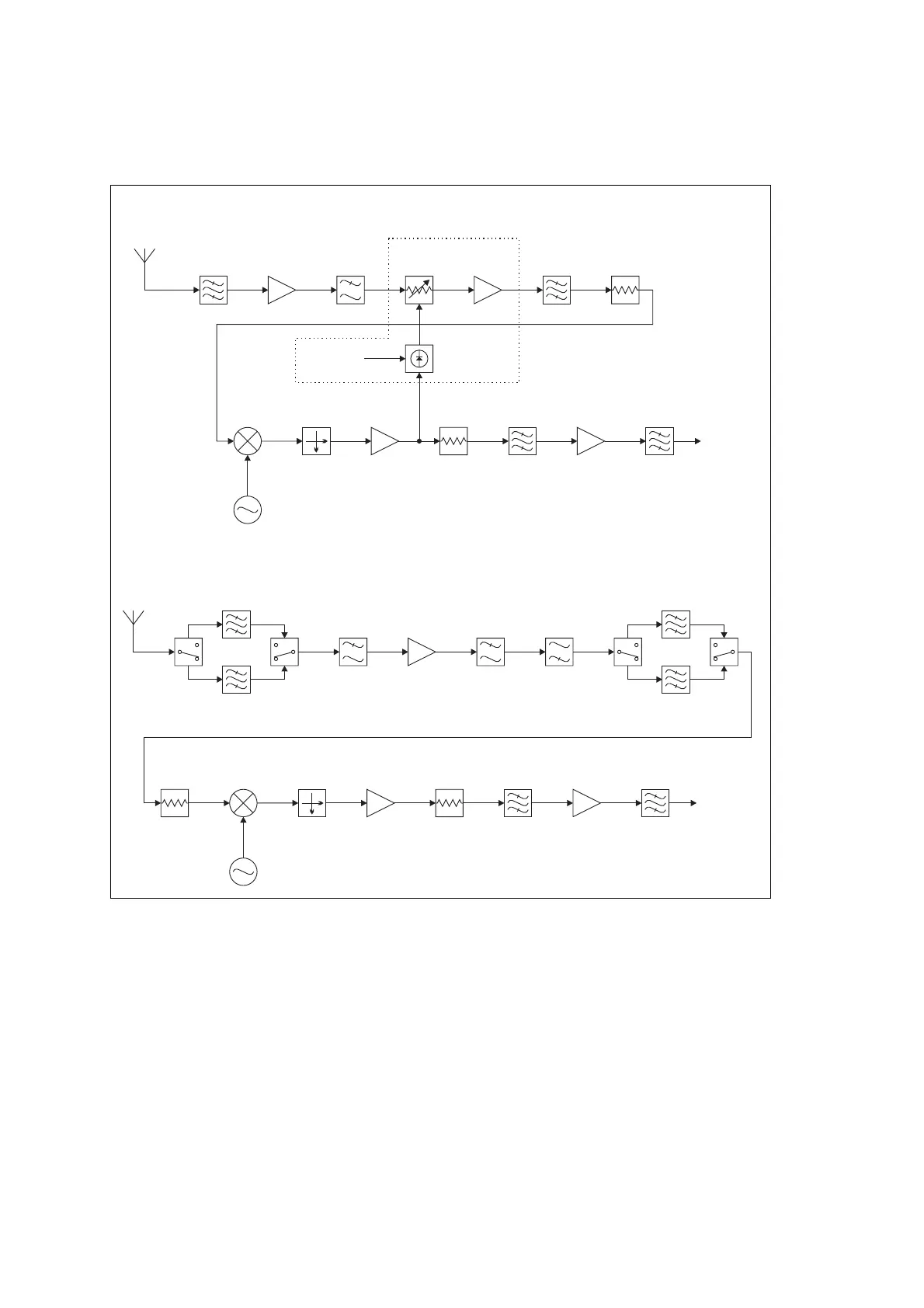
2.4 Receiver RF Circuitry - UHF Reciter
2.4.1 Front End
H-Band Reciter The incoming signal from the BNC connector is fed through a triplet helical
filter, followed by a simple low pass network which attenuates harmonics
and spurious responses from the preceding filter. The signal is then
amplified and passed through a low pass filter which provides immunity to
interference from higher frequency out-of-band signals. Automatic gain
control (AGC) is provided at this point by a PIN diode attenuator. The
signal is now amplified again in a second RF amplifier, and is then fed
through a band pass filter and attenuator pad to the mixer.
Figure 2.7 Reciter UHF receiver RF circuitry block diagram
Attenuator
Pad
RF
Amplifier
Low Pass
Filter
Low Pass
Filter
High Pass
Filter
SAW
Filter
SAW
Filter
SAW
Filter
SAW
Filter
SwitchSwitchSwitchSwitch
Attenuator
Pad
Mixer
Local Oscillator
Diplexer
Post-mixer
Buffer
Crystal
Filter
IF
Amplifier
Anti-alias
Filter
IF Output
RF In
Attenuator
Pad
Band Pass
Filter 1
Band Pass
Filter 2
RF
Amplifier 1
RF
Amplifier 2
Low Pass
Filter
PIN
Attenuator
AGC not fitted to
K band reciters
Attenuator
Pad
AGC Control AGC Detector
Mixer
Local Oscillator
Diplexer
Post-mixer
Buffer
Crystal
Filter
IF
Amplifier
Anti-alias
Filter
IF Output
RF In
H and K Bands
L Band

 Loading...


