TB8100 Service Manual Power Management Unit Fault Finding 235
© Tait Electronics Limited September 2006
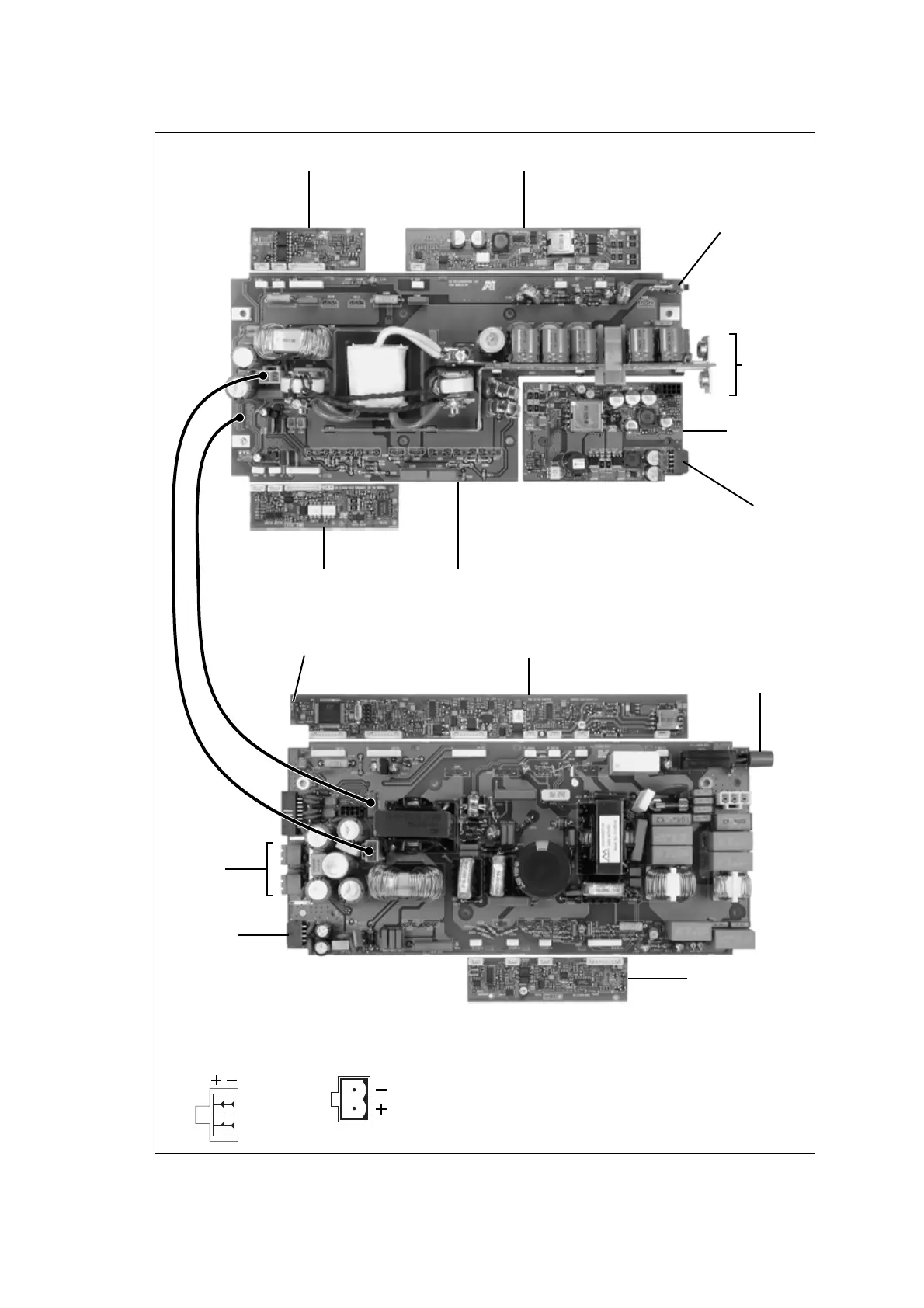
Figure 13.8 Checking the DC converter with microprocessor control
battery control card
DC control card DC converter board
DC input
PA outputs
+
–
DC on/off switch
on = up
off = down
Note:
In order to show as much of the circuitry as possible
in the photograph, the heatsinks and the
components normally attached to them are not
fitted, and the plug-in cards are not plugged in.
auxiliary power
supply board
standby power supply card
DC on/off switch
on = in
off = out
HVDC control and microprocessor card
PFC control card
reciter output
auxiliary DC output*
indicator LEDs
p
o
w
e
r
c
a
b
l
e
1
5
26
37
48
pins 1-4pins 5-8
*auxiliary DC output connectors
original type later type
r
i
b
bo
n
c
a
bl
e

 Loading...


